|
|
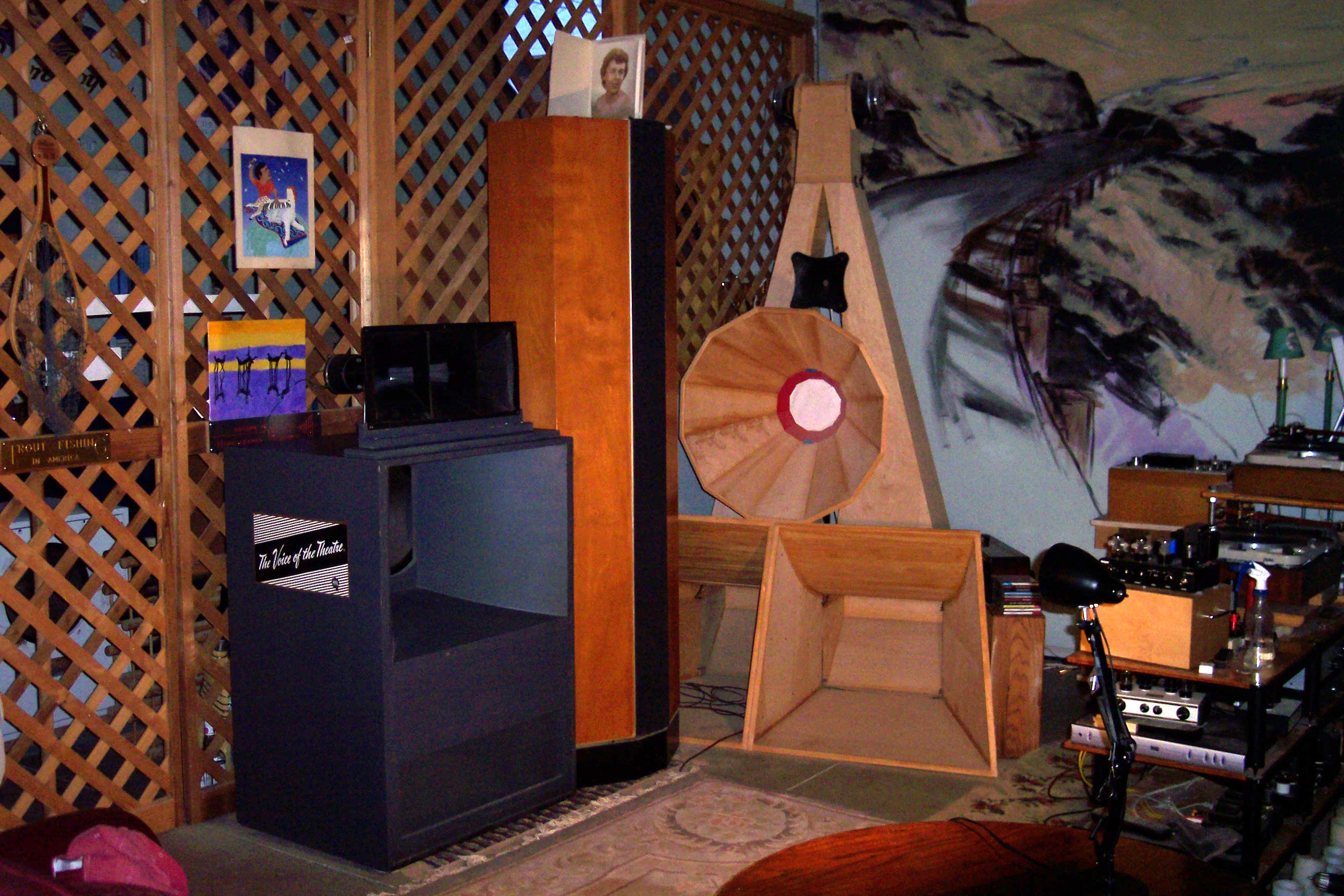
Altec A7 Voice of the Theatre Adventures
About the Speakers: This page is about a pair of Altec Lansing A7-500-8 Voice Of The Theatre
Speakers I set up in the Pete Riggle Audio listening room, known as The Garden of Earthly Delights. The speakers were
built by Altec Lansing in November of 1976. I am told that they spent many years in a church in Montana hanging up in
the ceiling space. These are two way speakers with crossover at 500 Hz. This particular pair uses model 825 cabinets
with a utility gray finish, model 416-8B Alnico woofers, model 511B sectoral tweeter horns, and model 802-8D
alnico magnet drivers. The speakers came with model N501-8A crossovers. I left the original crossover networks in
place, but play the speakers with crossovers built from a schematic originating with French audio legend Jean Hiraga. More
later about Messr. Hiraga and his crossover network design.Considering the age of the speakers, they are relatively blemish
free. As audio equipment goes, these speakers can be a fantastic bargain. In my room the speakers play a band width from 42
Hz to 12 kHz. With my big horn subwoofer the band width is 20 Hz to 12 kHz. Please note that I was mistaken when I
earlier said the woofers were the ceramic magnet 416-8C model.
These Speakers are Wonderful: Perhaps the first thing you should know about the A7 speakers is how wonderful
they are when outfitted with a crossover using the Hiraga schematic, and using crossover capacitors of high quality. The reflex
loaded bass goes adequately deep with rich timbre and beautiful midbass. I augment the bass with a giant subwoofer horn
located in a loft above and behind the listening room. The subwoofer helps in subtle ways, but the bass of the Altec A7 speakers
is quite good on its own. I had expected that the aluminum tweeter diaphragm would result in shouty highs. Nothing could be
further from the truth. The tweeters provide a very smooth top end, ranging from 500 Hz to about 12 kHz. This is an unusually
wide bandwidth, about 4-1/2 octaves, almost half of the audio spectrum. With the Hiraga crossover circuit and top performing capacitors,
the overall sound has a directness, immediacy, timbre, authority, nuance, ease and musicality that engage the listener,
and don't let go. Further, these speakers are capable of producing a big sound stage with great width, depth, nuance,
localization of instruments and voices and a great sense of space. The Altec Lansing people knew what they were doing. If
the products had been sold with good crossover networks, they would have been even more revered than they are today,
and the ebay prices would be out of this world. Perhaps the large size of the boxes and the utilitarian look has suppressed
audiophile enthusiasm. Mama may not like these speakers.
The Size of the A7 Speakers:
The A7 speakers are large, with a height
of 56 inches, a width of 30 inches, and a depth of 24 inches. The A5 speakers use a comparable bass box but are a little taller
because the tweeters are taller.The most common finish is a utility gray with no grill over the front of the woofer box, and
with the large 500 Hz tweeter horn exposed atop the cabinet. As woodworking goes, it would be relatively straightforward to
build a shell around each speaker with two sides, a top, and a grill, turning them into furniture. My wing-man Stephaen tells
me that I exaggerate the ease with which tasks can be accomplished. The A7 Speakers In Small Rooms: There is a prevailing myth that the A7 speakers do not work in small rooms and that the listener(s) need to be far
away from the speakers in order for the woofer and tweeter to blend. Do not believe it. I have
my pair set up with 9.5 feet between the centers of the speakers, and 9.5 feet from the front plane of the speakers to the
listener's ears. Jeff Day's A5 and A7 Speakers: I have been aware of the Altec Lansing Voice Of The
Theatre speakers for years. I enjoyed them at the movies when I was young. A friend had a beautiful pair with furniture finish
and grills when I was in my twenties. A mono VOTT unit played in the classroom when I took a music appreciation
class at the University of Washington in 1961. But for many reasons it never occurred to me to try a pair. Then I heard a
pair of A7 VOTT speakers last year in a very small room in the home of friend, audio reviewer, and audio blogger Jeff
Day. You can find Jeff at http://positive-feedback.com and at his audio blog http://jeffsplace.me/wordpress/. Jeff's
A7 speakers were originally built up by Altec Lansing as a furniture pair for Leopold Stokowski, who worked with Altec on
some of the first public live vrs. recorded performances at Carnegie Hall. The Stokowski A7 speakers are gorgeous, and
look deceptively small in the small room Jeff uses them in. Jeff is the third owner. Even in the small room, and even with
the stock crossover units (which leave much to be desired) I could hear the promise of these speakers. Jeff also has a pair
of A5 units, which use different components than the A7. The woofers of the A5 use more massive magnets than the woofers
of the A7. The A5 tweeter uses cellular horns (an array of many small exponential horns), versus the sectoral horns of
the A7 tweeters. The tweeter compression drivers of the A5 are more massive than the compression drivers of the
A7. With a Hiraga network in place, and some fine tuning, Jeff has his A5 units sounding mighty wonderful. I would compare
the A5 and A7 speakers (using the Hiraga crossover circuit and top performance capacitors) to chocolate. The A5 would
be very dark chocolate. The A7 would be medium dark chocolate. Although the A5 components are more expensive
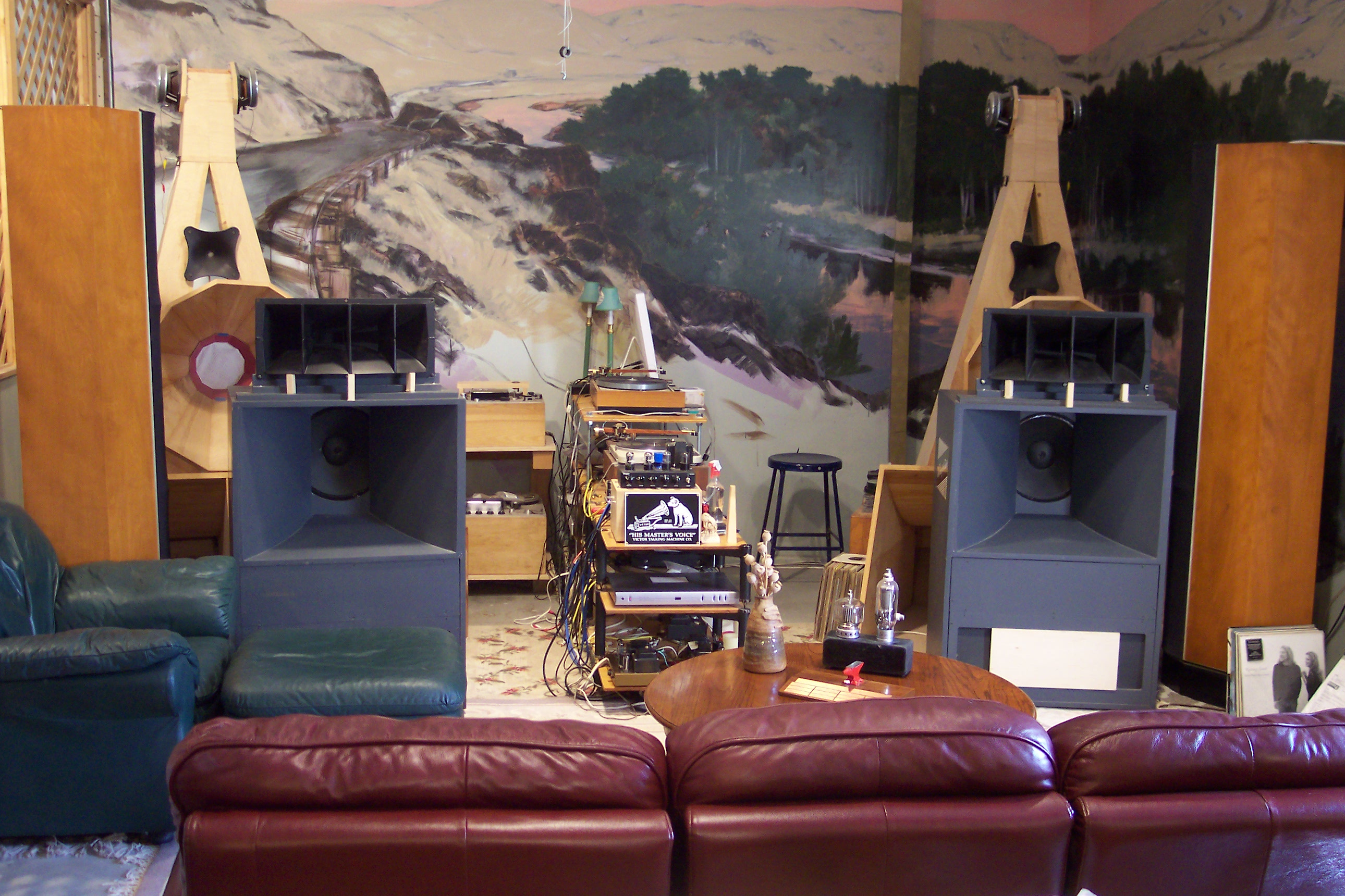
than the A7 components, I somehow prefer the A7. Jeff doesn't have to worry about that. He has both. The Sound of the A7: So how will I describe the A7 speakers
as set up in my Garden of Earthly Delights listening room: full bodied, rich, directly engaging, punchy, present, immediate,smooth,
sweet, musical, articulate, and nuanced, with a big sound stage, pin point localization of instruments, and lots of space.
The sound stage lies well behind the loudspeakers. That is what I hear. I can't speak for others. However my wing man,
Stephaen, who does not often throw bouquets at audio systems, said quietly the other day as we were listening "those
are good loudspeakers, Petie." If you can get out here to Eastern Washington State, give me a call, and I will give you
a demo. A
Little Perspective: Just to keep my praise for the Altec A7 and A5 speakers in perspective, I will tell you that Wilson
Sasha speakers driven by 150 wpc Audio Research Reference 150 SE amplifiers, with Russian KT150 tubes have educated me with
regard to "slam." On big music, played loud, the Wilson / Audio Research system casts a degree of shade on the
bass dynamics of the Altec A7 system speakers driven by the wonderfully musical 15 wpc Heathkit UA2 amplifiers (using
old stock Amperex Bugle Boy EL84/6BQ5 output tubes). I can't tell you much more, as the set up of the two systems is so
different as to defy comparison. I will say that I have not yet heard the Wilson system provide some of the more subtle musical qualities
provided by the Altec system, nor have I heard the Altec system do the "slam" provided by the Wilson system. One
needs to know what one wants. We have not yet heard big power Audio Research amplifiers on the Altec speakers.
But my modest 30 wpc triode wired 6550 push-pull amps do not sound as good as the 15 wpc ultralinear Heathkit UA2 amplifiers
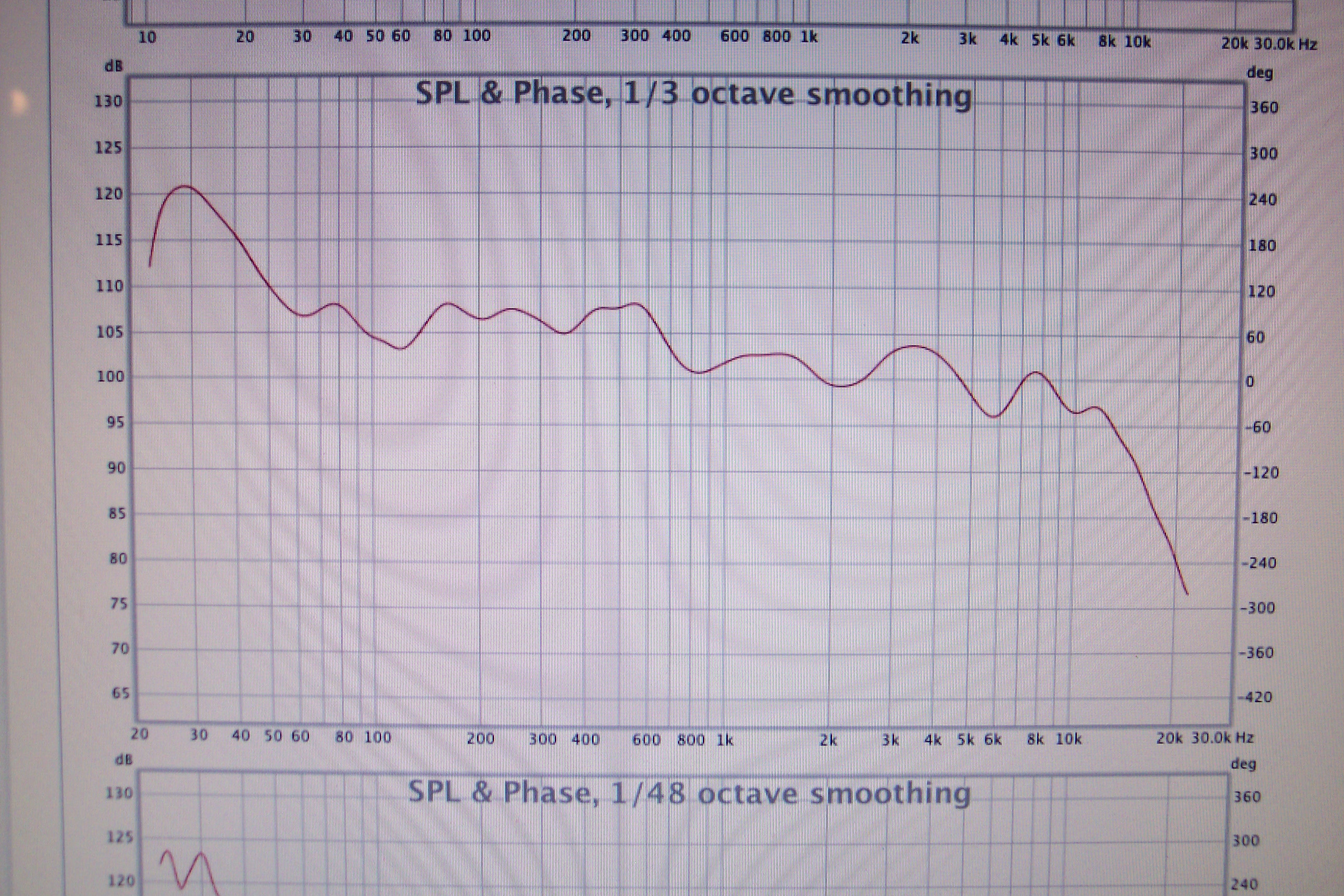
driving the Altec speakers. Sound Pressure Measurements: Gary Ford, a very competent sound systems professional living out our way (200 shows a year for
many years), is good at speaker measurements. Gary also has a new audio store Epic Audio (sales@epic-audio.net , telephone 509 539 1214) with many interesting offerings. The Epic Audio web site is: www.epic-audio.net. Gary dropped by recently and did a measurement of the Altec A7 speakers in the Garden of Earthly Delights. I knew that
these speakers sounded good, but did not know how they might measure. From the listening position they measured very well
indeed, with and without the giant horn subwoofer in operation. The frequency response was from the low forties to about 12
kHz without the subwoofer. The drivers for this measurement are the 416-8B 8 Ohm alnico magnet woofer, the 802-8D 8 Ohm
alnico magnet compression driver, and a pair of Altec 415 biflex drivers for the subwoofer horn. Why use a wide range driver
for a subwoofer? It was what we had on hand when the woofer was built. The measured system frequency response with the woofer
engaged is from the 20 to 12 kHz with the subwoofer. From about 50 Hz to 12 kHz the response drops in an almost straight
line on a log-log frequency response graph (the so called Bode diagram we audiophiles see so often), falling about 1.38 dB
per octave.The L-pad setting for the tweeter is the one that makes the speaker sound best. I asked Gary about the gradually
falling response. He advised that a smoothly falling response makes for good listenable sound (and is targeted by sound
reinforcement professionals). My experience has also been that a smoothly falling response, or at least a wide band reduction of frequencies
centered on about 3 or 4 kHz, makes a system sound lovely. By
wide band, I mean the output might start falling at 500 Hz, reaching a trough of maybe 3 dB at 3.5 kHz, gradually returning
to the baseline at 9 or 10 kHz. Every effort I have made at flat loudspeaker response equalization has ended in disaster.
Gary's measurements were another learning experience for me, reinforcing observations I had made before (about the desirability
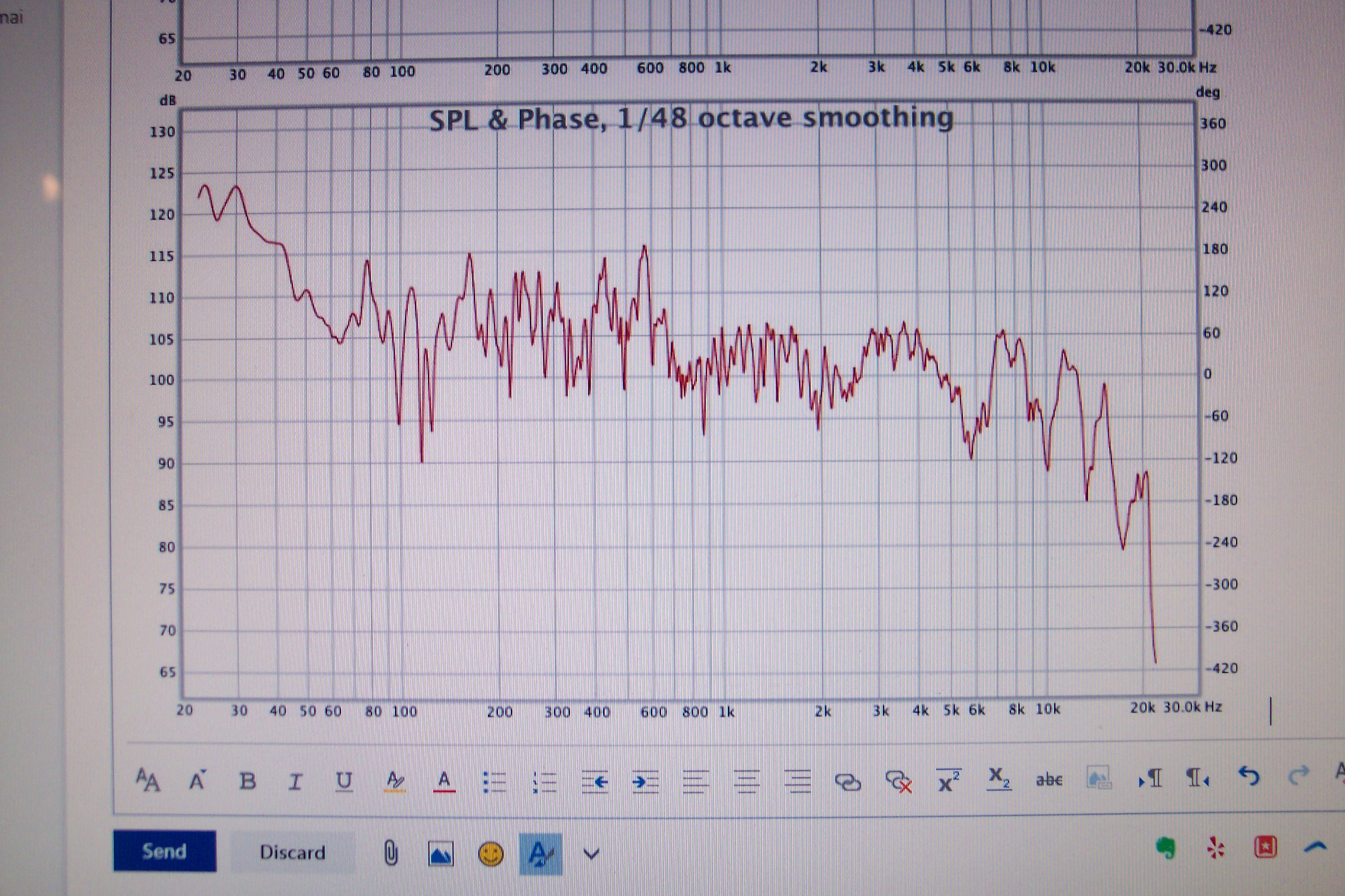
of having the system response fall with increasing frequency), but about which I was tentative. Above 10 kHzThe Hiraga network provides a rising drive signal to the
tweeter, which might add a little extension to the tweeter output at these frequencies. Looking at the smoothed frequency
response plot below, and noticing the shelving of frequencies above the 500 Hz. crossover point, one might suspect that raising
the tweeter level about 3 dB would give a better result. It certainly would provide a flatter measurement. However the system
sounds best with the tweeter set where it is. If one were a hound for bright high frequencies, it might make sense to
turn the tweeter up just a little. On a different point, the rising output of the subwoofer at very low frequencies helps deal a blow to the Fletcher-Munson
effect without exciting boom frequencies in the 50 Hz range. The A7 response curve immediately below is taken at the listening sweet spot with a pair
of A7 speakers in the Garden of Earthly Delights with the big horn subwoofer playing.
 Reduce the Reflex Port Area:
Vented enclosures like the bass box of the A5 and A7 speakers need to have the correct vent area. The factory provided area of 208 square inches for the bass box port of the A5 and A7 speakers is too large for best results. With the large area the bass was boomy and poorly defined.
An article on the A5 by John Stronczer suggested that it might be desirable to reduce the port area. My first attempt at reducing the port area was accomplished by inserting an 8-1/8 inch by 17.5 inch board
of 3/4 inch plywood into the center of the slot provided by the factory. This left two 34 square inch vents, one on
each side of the plywood board. The board was friction fit into place using card stock shims as required.This gave
a very nice bass response with which I was quite satisfied for an extended period. A timeworn methodology for adjusting vent area is to do woofer-in-box electrical impedance sweeps, adjusting the port area to achieve two roughly equal impedance bumps. This was done for me by Gary Ford, mentioned above. With the vent at either the original 208 square inches or at 64 square inches we found only one impedance bump . Reducing the port area of the A7 speaker to 34 square inches resulted in two roughly equal impedance bumps. My initial impression on selected pieces of music was that 34 square inches of port in each box was preferable to 68 square inches. More recently I happened to be playing a succession of pieces, all with a lot of very low bass material. What I heard was disturbing. Even with the big horn subwoofer turned off, I was hearing some of what I can only call grotesque bass undertones. Upon opening up the port area to the previous value of 64 square inches, the bass returned to a very pleasant presentation on all the material that I played. So we are back at 64 square inches, and very pleased. With good crossovers and the right setup, the A7-500 speakers are really wonderful. Completely non-clinical, with a big full rich bottom end, lots of nuance and inner detail, good localization of performers, big space, and a really musical presentation.
Praise for the Altec Lansing A5 and A7 speakers:
To back up my praise for the Altec Lansing A5 and A7 loudspeakers, let me suggest that you read an article authored by John Stronczer of Bel Canto Design. The article was published in Positive Feedback some years ago. John set up a version of the A5 based on communication with Jean Hiraga. The following URL will get you to the article:
http://wajonaudio.webs.com/Voice%20of%20the%20theatre.pdf
Also, wajonaudio has a nice article on the A7:
http://wajonaudio.webs.com/RETURN%20of%20a%20LEGEND%20-%20ALTEC%20A7%20Speaker-System.htm
These articles express the respect the authors have for the A5 and A7 speakers.
About Jean Hiraga:
Looking for biographical info on Jean Hiraga turned up an excerpt from an article by the redoubtable Lynn Olson. I encourage you to read the article:
http://www.nutshellhifi.com/library/europe3.html
Here is the excerpt selected from Lynn Olson's article:
"Jean Hiraga, long-time editor of "Revue du Son", gave a truly inspiring talk and musical presentation - a highlight not just of this show, but any show. Why? Jean Hiraga, son of a Japanese father and a French mother, was in a unique position to bridge the European and Japanese world of audio, speaking both languages fluently, and with a deeply felt attachment to the art and craft of high-fidelity sound. He was exposed to Japanese triode culture in the mid-Sixties - twenty-five years before the American triode revival in the early Nineties - and brought it back to Europe."
"He wrote some of the first articles analyzing the desirable harmonic characteristics of direct-heated triodes, and is directly responsible introducing the sound of DHTs to France, Italy, in time, the rest of Europe, and finally, to the English-speaking audio world. Without Mr. Hiraga, there would have been no Sound Practices magazine, no VSAC, and no ETF - the English-speaking audio world would be nothing but high-watt mainstream and home-theater equipment. Fortunately for music lovers everywhere, events took a different "
About Crossovers for the A5 and A7:
A circuit by Hiraga for a crossover for A5 speakers with the 8 ohm drivers is included in John Stronczer's article. John also shows a crossover for A5 speakers with 16 ohm drivers. Neither of these schematics shows an L-pad for the tweeter, which has turned out to be a necessity for my A7 speakers and for Jeff's A5 speakers.
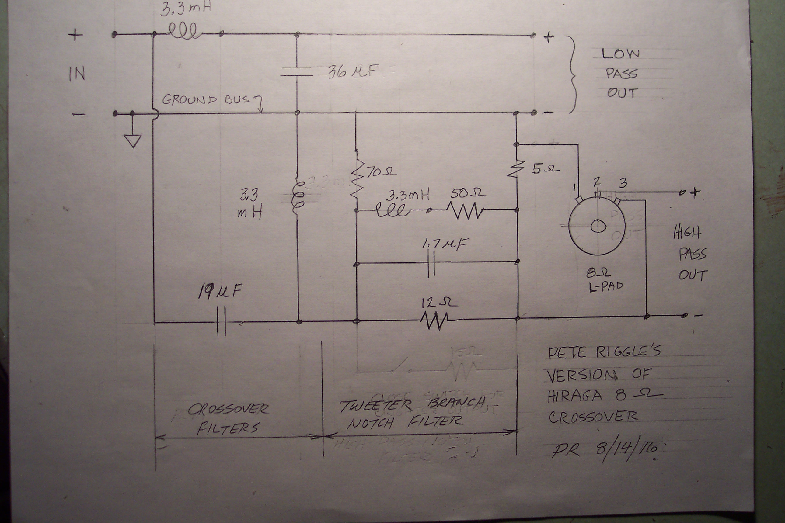
When faced with the need for improved crossovers it occurred to me that the notch filter Hiraga included in his A5 crossover would possibly be a welcome addition to many 2 way speaker systems, which often are too hot in the 900 Hz to 9 kHz range addressed by the notch filter. So I decided to try the Hiraga's circuit for the A5 speakers A7 speakers using component values specified by Hiraga. Here is the circuit for 8 Ohm speakers, with the L-pad included. The image may be difficult to read, so here are the values: In the low and high pass branch the inductors are 3.3 mH. The capacitor in the low pass circuit is 36 uF. The capacitor in the high pass circuit is 19 uF. The notch filter inductor is 3.3 mH in series with a 50 Ohm resistor. The notch filter capacitor is 1.7 uF. The notch filter resistor is 12 Ohms. The resistors to ground are 70 Ohms and 5 Ohms. The L-pad is 8 ohms. Note that the tweeter is connected with its positive terminal going through the L-pad to ground.
How to determine the positive terminal of an 802 driver? For the 802-8D compression driver the + terminal is the one marked with the number 2. Looking at the rear of the compression driver with the terminals at the top, the + terminal is on the right. Mark it with some red tape or paint. I notice that for the later 802-8G driver the + terminal is marked in red, and located the same as for the 802-8D driver. On the Lansing Heritage Site one of the forum members, jimd, has the following advice:
"In the case of Altec cone drivers marked with terminals marked 1 and 2, 1 is hot as the magnet is behind the cone.In the case of the 802 and other "inside out" type HF drivers, where the builders routed the sound output through the magnetic assembly, the magnet is in front of the diaphragm instead of behind it like conventional drivers. Therefore, to get positive pressure at the exit of the Altec HF driver, one must apply positive voltage to terminal 2. Confusing? Yes. It was really nice when they went to Red or + on the hot terminals."
For a 16 Ohm crossover, double the values of the inductors, resistors, and L-pad, and halve the value of the capacitors.
The circuit shown below, based on Hiraga's 8 Ohm crossover circuit, includes the tweeter L-pad.
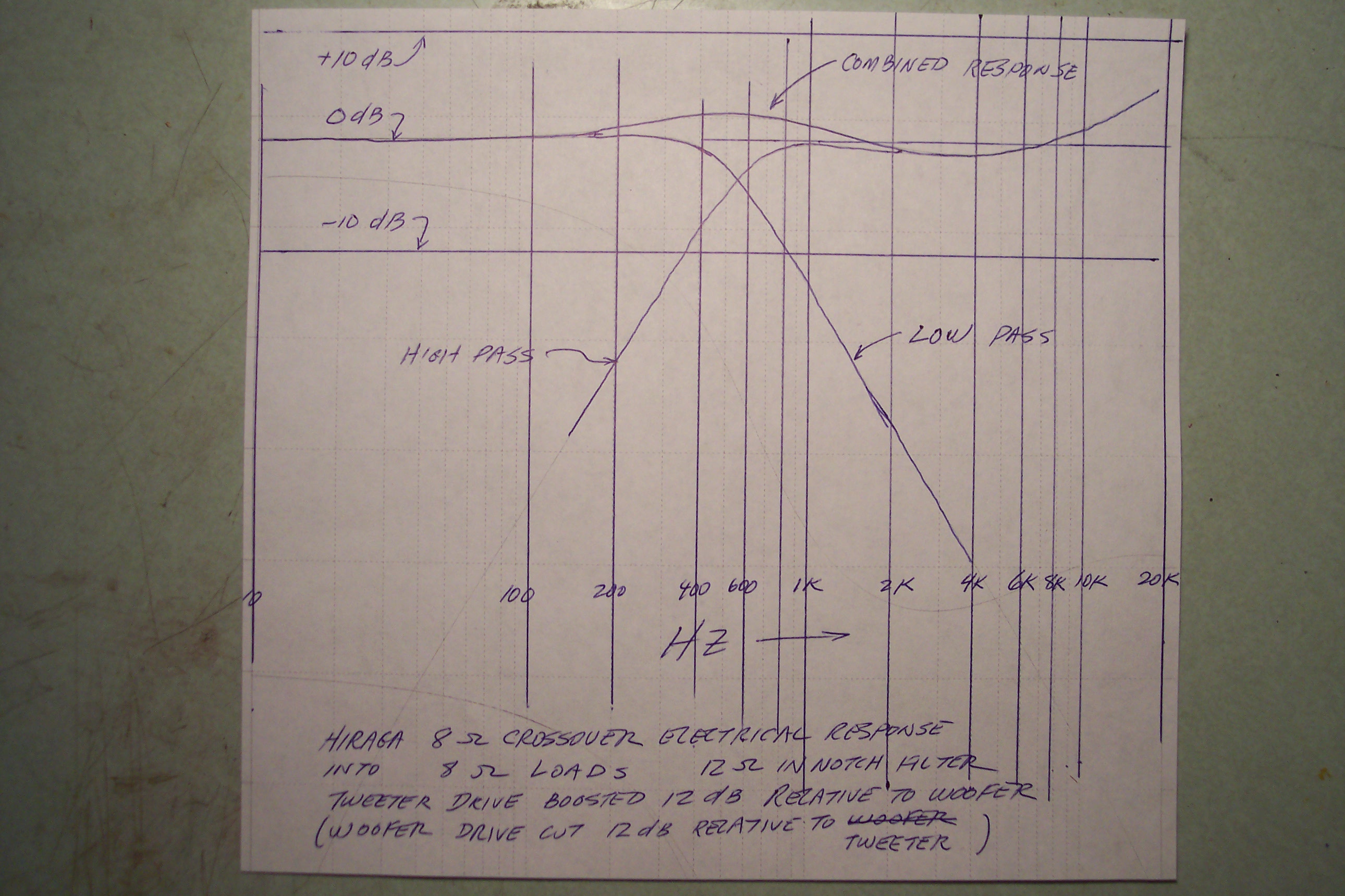
The calculated electrical response of the Hiraga 8 Ohm crossover into 8 ohm electrical loads is shown in the Bode diagram below. These results were calculated using the Spice program. Pure resistance, inductance and capacitance were assumed. Response curves were also calculated adding parasitic inductance to the crossover resistance values and adding measured speaker driver inductance values to the load resistance values. The difference between the response curves with and without the inductance corrections was small. In the real world the electrical output to the tweeter would be 12 dB below that shown on the diagram. To get the a picture of the implied pressure response coming from perfect speakers with equal on-axis sensitivity the calculation was made with the voltage of the woofer load resistor tapped at the 1/4 point. One quarter power corresponds to a sensitivity reduction of 12 dB.
One way to look at this would be to recognize that the tweeter sensitivity is more than 12 dB above the woofer sensitivity. However we use the tweeter L-pad to trim the tweeter sensitivity to a desired value. If we trimmed the tweeter to a sensitivity 12 dB above the woofer, and if the speakers presented resistive loads, measured flat on-axis, and the sound combined as if from the same source, these are the speaker response curves we would expect when drive by the Hiraga circuit through a perfect power amplifier.
What is the point of all this? We want to know the contribution to frequency response attributable to the crossover network.
Crossover Capacitors:
To get wonderful sound the capacitors need to exhibit very high performance. They need to sound musical. Capacitors are often the weakest link in an audio component. On the basis of listening tests of capacitors using my Altec A7 speakers in the Garden of Earthly Delights, I have laid in a stock of high performance capacitors constructed with paper, film, and oil, which I sell as Pete Riggle Personally Selected Loudspeaker Crossover Capacitors. Available capacitors include Type 1 capacitors , which are preferable for the high pass branch, my Type 2 capacitors, which are preferable for the low pass branch, and my Type 4 caps which work well for the notch filter. I will soon add a page describing and offering these capacitors, and will include the capacitors in my price list. My SPICE calculations show that +/- 15% deviation in capacitance from the values shown on the schematic has little effect on the calculated crossover response. Don't be afraid to round up or down a little as needed to obtain capacitors to do the job. I will mention here that for the notch filter capacitors in his Altec A5 speakers Jeff Day has tried Dueland Cast capacitors with tin plated copper plates. Jeff is quite pleased with the resulting sound. These capacitors are still in the prototype stage and at the time of writing are not commercially available. When offered they may be quite expensive, and out of range for some of us.
Low Pass Crossover Inductors:
For inductors for the A7 crossovers I suggest ERSE Super Q steel core units for the low pass branch. For the low pass branch of the A7 speakers, lower DC Resistance (DCR) of the inductor is better. Low resistance in low pass inductor limits degradation of woofer electro-dynamic damping. I have had good success with this same type of inductor for the main inductor of the high pass branch.
For his A5 Hiraga type crossovers Jeff Day used identical air core inductors in the low pass, high pass, and notch filter locations. It is worth mentioning that the slightly greater DC resistance of the air core inductor in the low pass location of the A5 crossover might not be detrimental. It is possible that the driver of the A5 has too much magnet for best bass response, which can be offset by a little more DC resistance.
High Pass Crossover Inductors:
It is probably preferable to use air core inductors for the main inductor and the notch filter inductor of the high pass branch. I happen to have used steel core inductors for the main crossover inductor of the high pass branch, and air core inductors in the notch filters.
For the notch filter one can use a fairly high resistance inductor, using the internal resistance of the inductor as part of the 50 or 100 ohms in series with the inductor.
If you have inductors on hand that have higher inductance values than required, it makes perfect sense to unwind the inductor until it measures the required value. And if, for example, you needed a 3.3 mH inductor, but could buy only 4.0, it makes perfect sense to buy the 4.0 and unwind it to 3.3 mH. Low cost capacitance/inductance meters are available; check on ebay.
Sources of Inductors:
ERSE Super Q steel core inductors are available through Parts Express. Solen air core inductors are available directly from Solen, a Canadian company. I am contemplating buying spools of 24 gage copper magnet wire from Remington on eBay and unwinding them to get the inductance needed in the notch filter. The notch filter inductor is used in series with a resistor. The resistance of the 24 gage wire can be used to substitute as part of the specified resistance.
Crossover Resistors:
You will want to use wire-wound power resistors with a power rating of 5 or 10 watts or more. These resistors come in a number of varieties. The type with the metal heat sink are convenient to mount, but are expensive. The glossy brown ceramic type such as the Ohmite resistors are pretty. I have had fine success using the least expensive type, which is the sand cast resistor in the rectangular ceramic box. You could use non-inductive resistors; however my SPICE calculations show that the inductance of the regular resistors does not significantly change the response curves of the crossover. I measured a bunch of different resistor types in different values and for all of these resistors found that the inductance associated with the resistors was uniformly .018 or .019 mH for each Ohm of resistance. None of these resistors was marked as non-inductive.
Sources of Power Resistors:
There are many places to buy power resistors. I happen to source mine from All Electronics Corporation which has a nice little catalog with many interesting things. You could call 800-826-5432 and ask for a catalog. The company also has an on-line ordering system.
Sources of L-pads:
I have had fine success with inexpensive L-pads out of my parts box. The 100 watt units sold by Parts Express should be just fine.
This page is a work in progress. I will stop at this point. Soon I will be adding more detail. Until then . . . Happy Listening.
Building Crossovers:
The following discussion may be helpful to those planning to build their own crossover boards. I recommend using 3/4 inch plywood to mount the components.
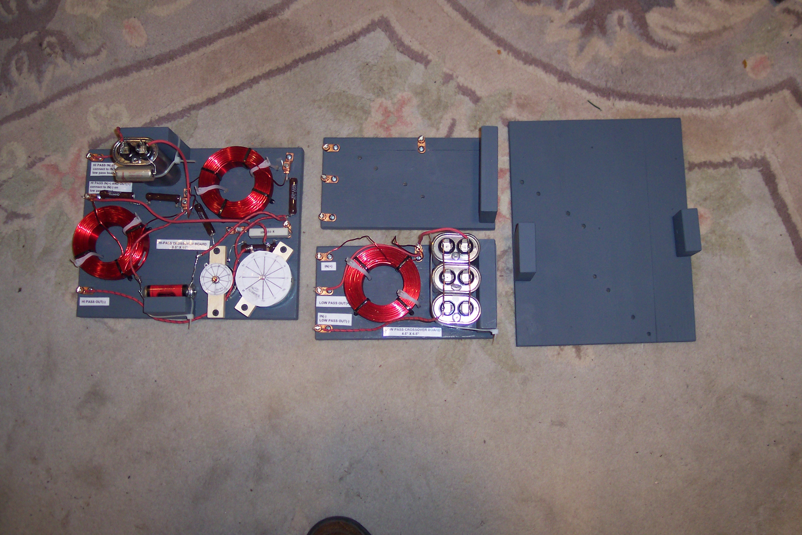
Shown below, are layouts and photos of crossover networks designed and fabricated for Jeff Day's A5 Voice Of The Theatre speakers.
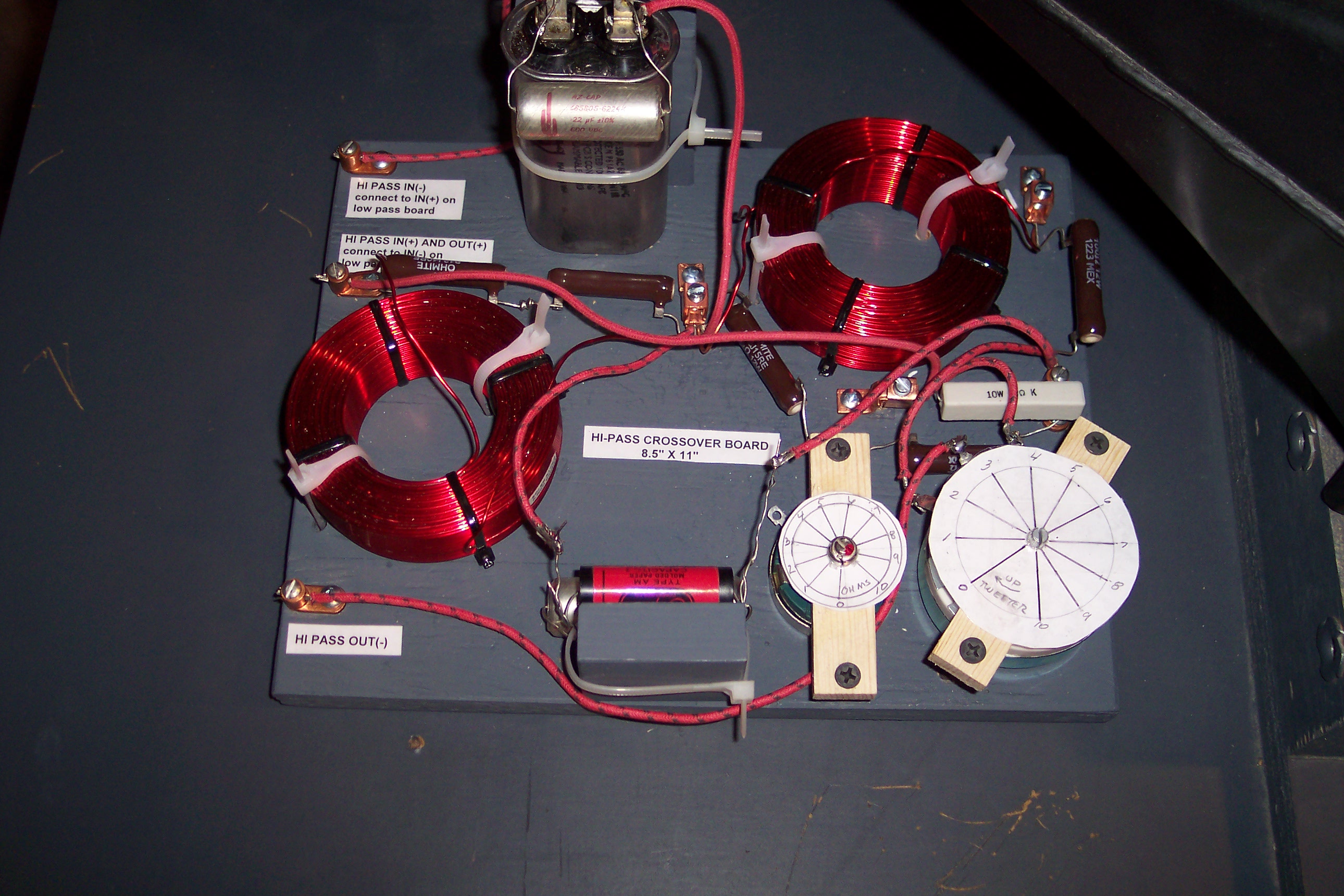
Let us start with the first image. I put Jeff's crossovers on two boards; one board is for the low pass network; one is for the high pass network. I separated the low and high pass networks onto two boards so that the boards can hide behind the tweeter horn, one on each side of the tweeter support stand. In the image below you see one completed set of boards, and one set not yet populated:
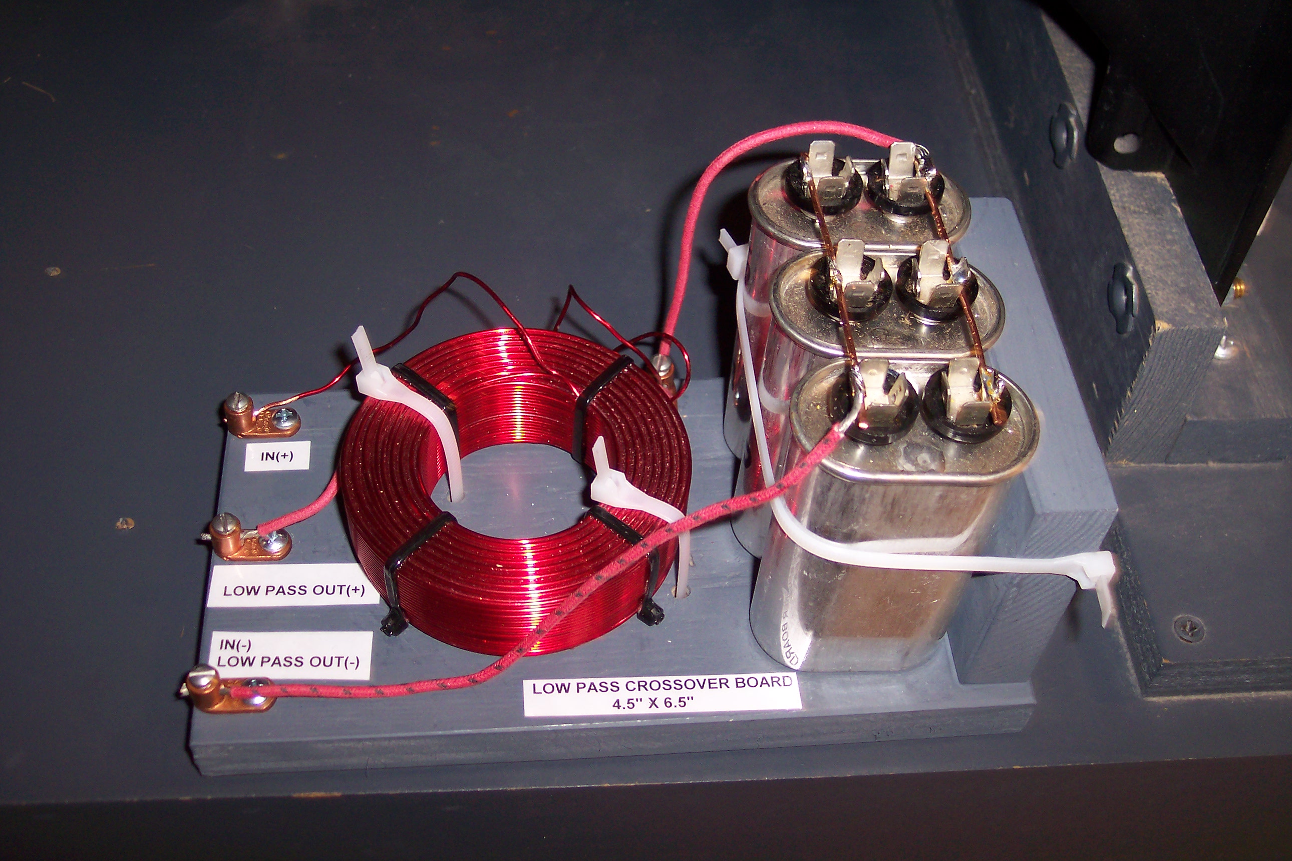
The images below show the low and high pass boards individually:
The images below show the low and high pass boards individually:
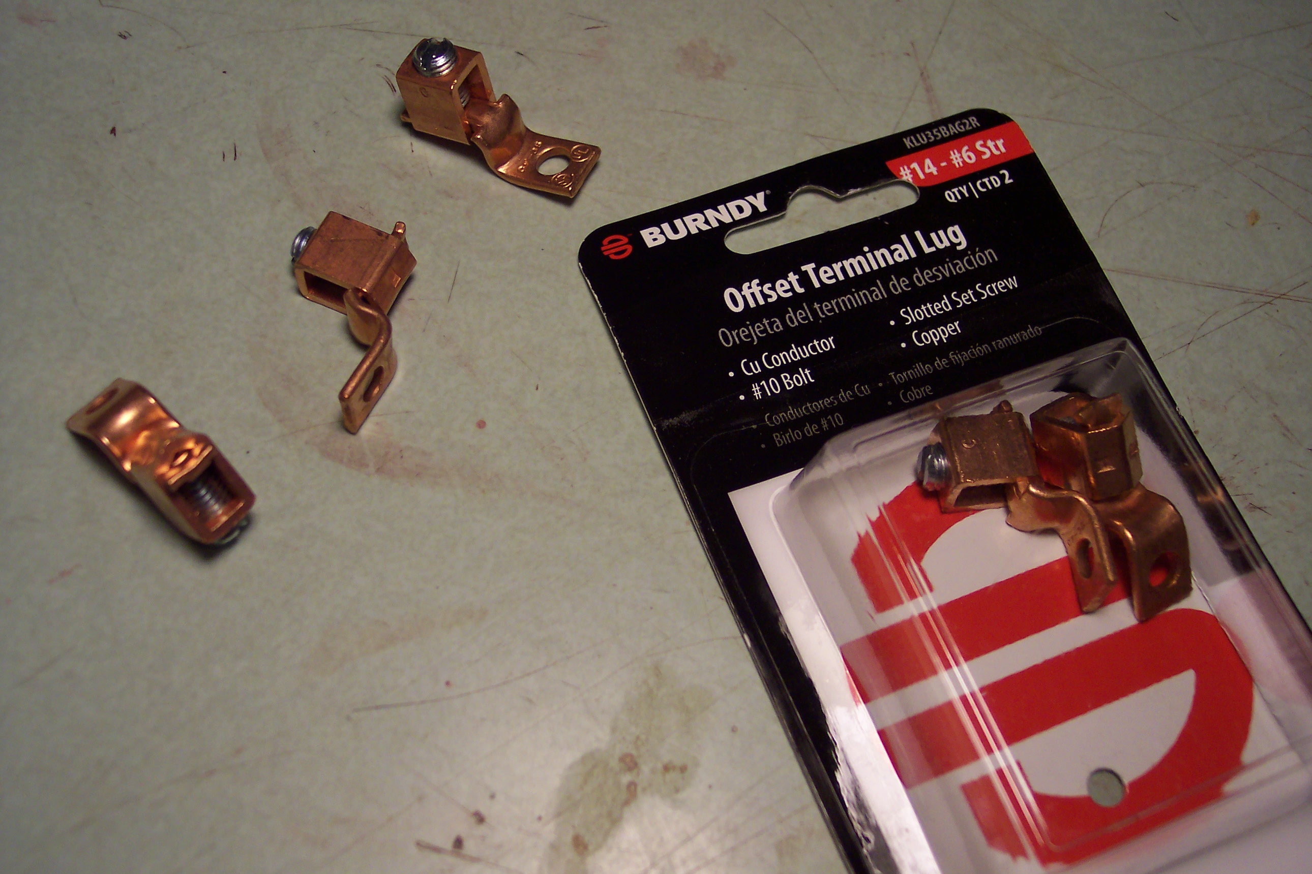
I set Jeff's boards up so that any component can be removed and replaced without soldering. This makes it convenient if one wants to try different components. In the above two images you can see that the chokes are strapped down with zip ties which run through holes in the board. For Jeff's boards I chose to secure the capacitors to blocks screwed to the board from below with drywall screws. Note that I put the input and output terminals on the same end of each board. This makes for tidy wire runs into and out of the crossover board, but causes the layout of the components to appear very different from the layout of the schematic, which can be confusing when trying to follow the circuit on the board. I used terminal lugs provided to me by Jeff (see the images above). These are nice looking lugs, which allow through wires; but they suffer from limited throat capacity, which is a problem. I recommend using lugs like the ones shown in the image below. The lugs in the image below have a large throat. They are designed with a tongue and a collar. The tongue can be screwed to the crossover board with a No. 8 or No 10 pan head wood screw with a length of 3/4 inch. You could use 1/2 inch screws if you can not find 3/4 inch screws. The collar encircles the tongue and has a set screw has a set screw that presses the tongue against the bottom of the collar. These lugs are designed to have the wires enter below the tongue. Running the wires below the tongue prevents the user from using a through wire. If the user wishes to use a through wire (sometimes I use No. 12 solid wire, from Romex house wiring, as a bus bar), one could run the through wire(s) above the tongue. I purchased these lugs from Home Depot, at a price of $1.97 USD per pair. Lugs like those in the image below are also available from McMaster Carr, but at a higher price. The disadvantage of the big box store is that they may not have enough terminals on the shelf to meet your needs.
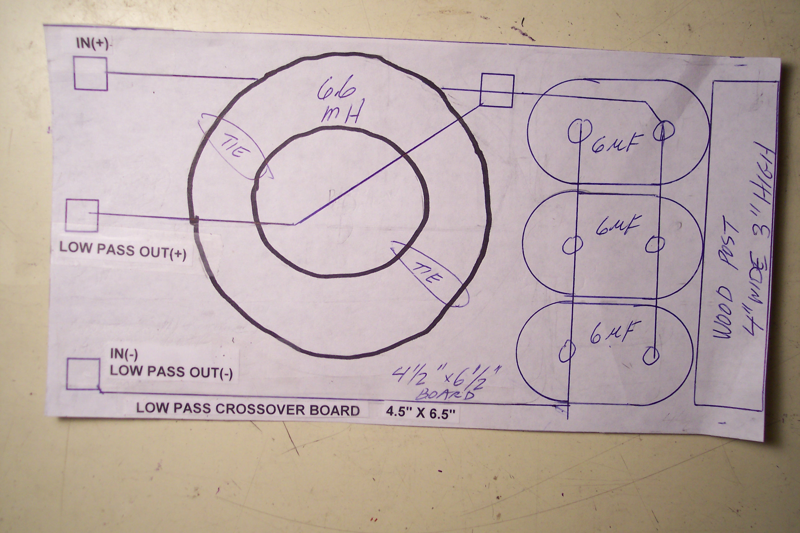
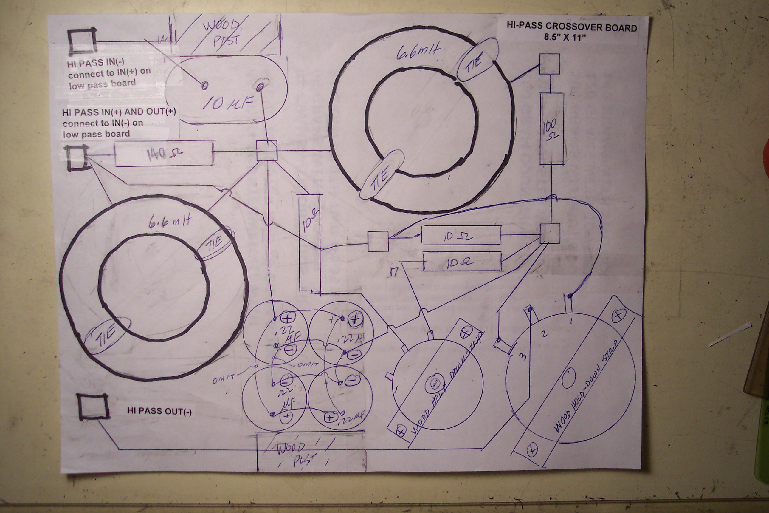
Attached below are crude layouts of the crossovers I built for Jeff Day:
A couple of things worth mentioning:
Jeff's high pass crossover has a potentiometer used as a variable resistor in series with two 10 ohm resistors to allow him to fine tune the nominal 24 ohm resistor in the Hiraga notch filter. As you can see in one of the photographs, my technique for mounting potentiometers and L-pads is to cut wood strips to go across the top of the potentiometer and L-pad. Each wood strip is about 3/4" wide and 1/4 inch thick, and long enough to clear the body of the device. I drill a hole in the center of the strip to clear the shaft bushing, and drill a hole at each end to accept drywall screws long enough to do the job. Note that I made dials out of file card stock to indicate the settings of the potentiometer and the L-pad. I glued the dials to the top of the wood strip.
Conclusion:
I think this wraps up the A7 and A5 discussion, until I make further improvements.
|