|
|
Stringtheory(tm) Bearing Repair
About
the Stringtheory(tm) Bearing: Several families of tonearm products use string bearings. In addition to the Pete Riggle Woody tonearms, the
most noteworthy of these are the Well Tempered tonearms by Bill Firebaugh, and the magnetically stabilized and damped
tonearms of Frank Schroeder. Another interesting design using a string bearing concept is a Japanese design in which the string
tethers the bottom of the tonearm wand at the pivot point, with the considerable weight of the tonearm wand and counterweight supported
by a very strong magnet above the wand at the pivot point. This concept is used in certain arms produced by Clearaudio. The Stringtheory
bearing is novel and unique in that the string is very short (close coupled), and that the bearing is uniquely configured to
provide significant rigidity to resist lateral loads. The
Stringtheory Concept: We have been reluctant to publish details of the Stringtheory bearing, considering the design to be proprietary.
However we do want our customers to be able to make a repair on their own if they so choose. Also, we think the design of
the bearing may be of interest to DIY hobbyists for non-commercial use, an activity we have no objection to. So
here are the details: Four strings emanate from a square array in a small brass button supported by the anti-skate adjustment knob centered
on the upper platform. These four strings converge to an apex, forming an inverted pyramid, and then diverge in an upright
pyramid which terminates in a square array in a small brass button secured to the top of the tonearm wand. The
light load of stylus drag is insufficient create slack in any of the strings employed by the bearing, resulting in excellent
radial stiffness. Under any reasonable radial load, the strings remain in the taut state. See the diagram below: 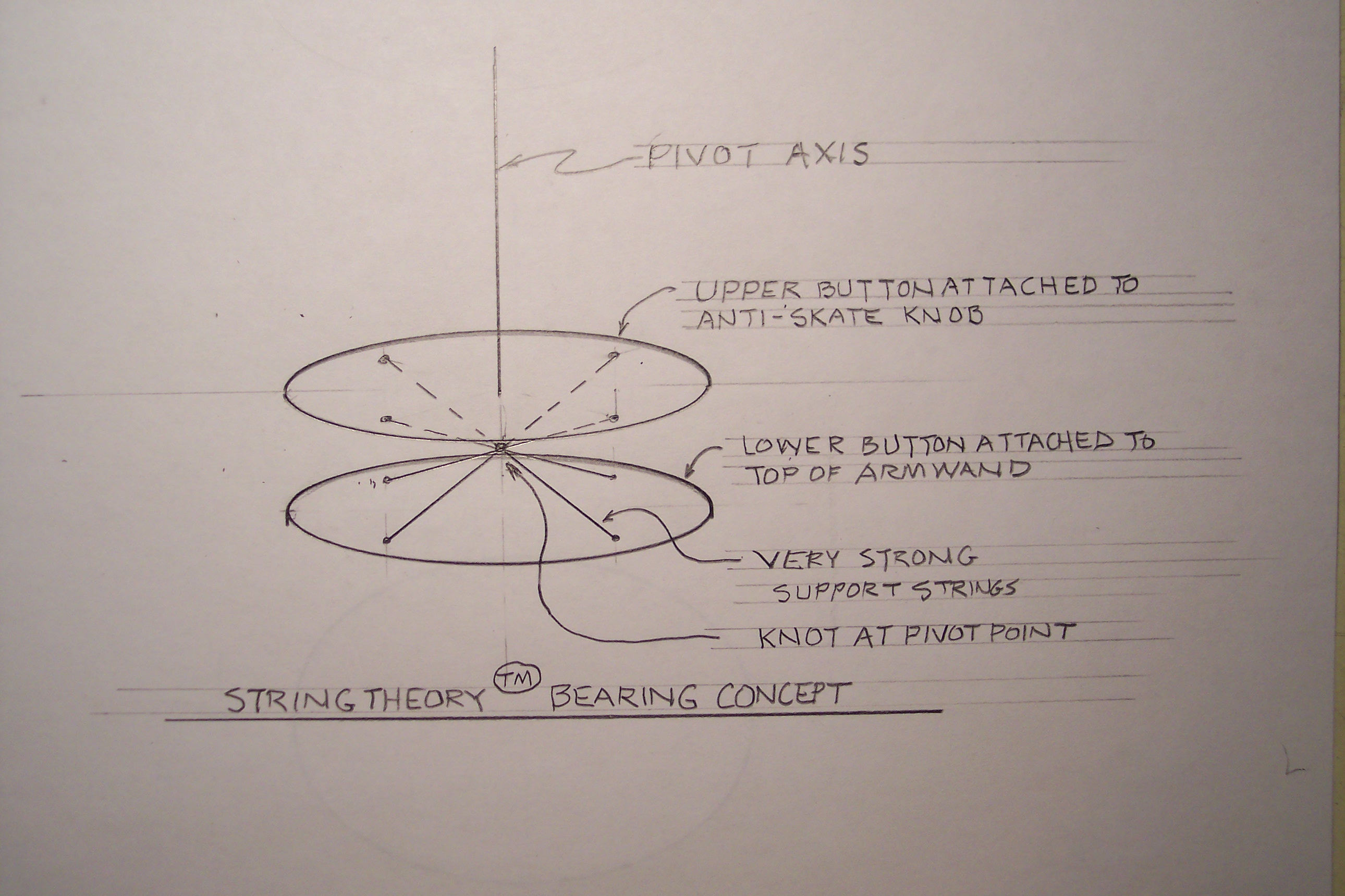 Damage to Woody Tonearm String Bearings is Rare: The string used for Stringtheory bearings uses one of the
strongest commercially available fibers. The trade name is Dyneema (tm). The claim is made that Dyneema is 40 percent
stronger than Kevlar. The combined vertical breaking load of the Stringtheory Bearing is 40 pounds. Nonetheless, a few
of these bearings have become damaged, sometimes in shipping, and sometimes because of excessive rotation of the anti-skate
knob. We have refined the packaging to avoid failures from shipping loads, and do caution against excessive rotation
of the anti-skate knob (multiple turns). Something to note about string bearings is that it tends to be obvious when the bearing is damaged. This is not always
true for gimbal bearings. Bearing Repair Policy: On request, without charge, we will provide a replacement bearing capsule in exchange
for a bearing capsule with broken string. We request the user to return the bearing capsule being replaced. Replacement
of the bearing capsule without shipping the tonearm is quick and easy process. Also, with this web page we are publishing details
on how to re-string a Woody Tonearm bearing. Upon request and at no charge, we will mail sufficient string
for bearing re-stringing by the user. For future Woody Tonearm deliveries, replacement string will be included. Publishing the details of our
string bearing technology poses a small risk that another tonearm manufacturer will use our technology to compete
with us (not that such competition would have a significant effect on our sales). We would prefer for that not to happen. Replacement
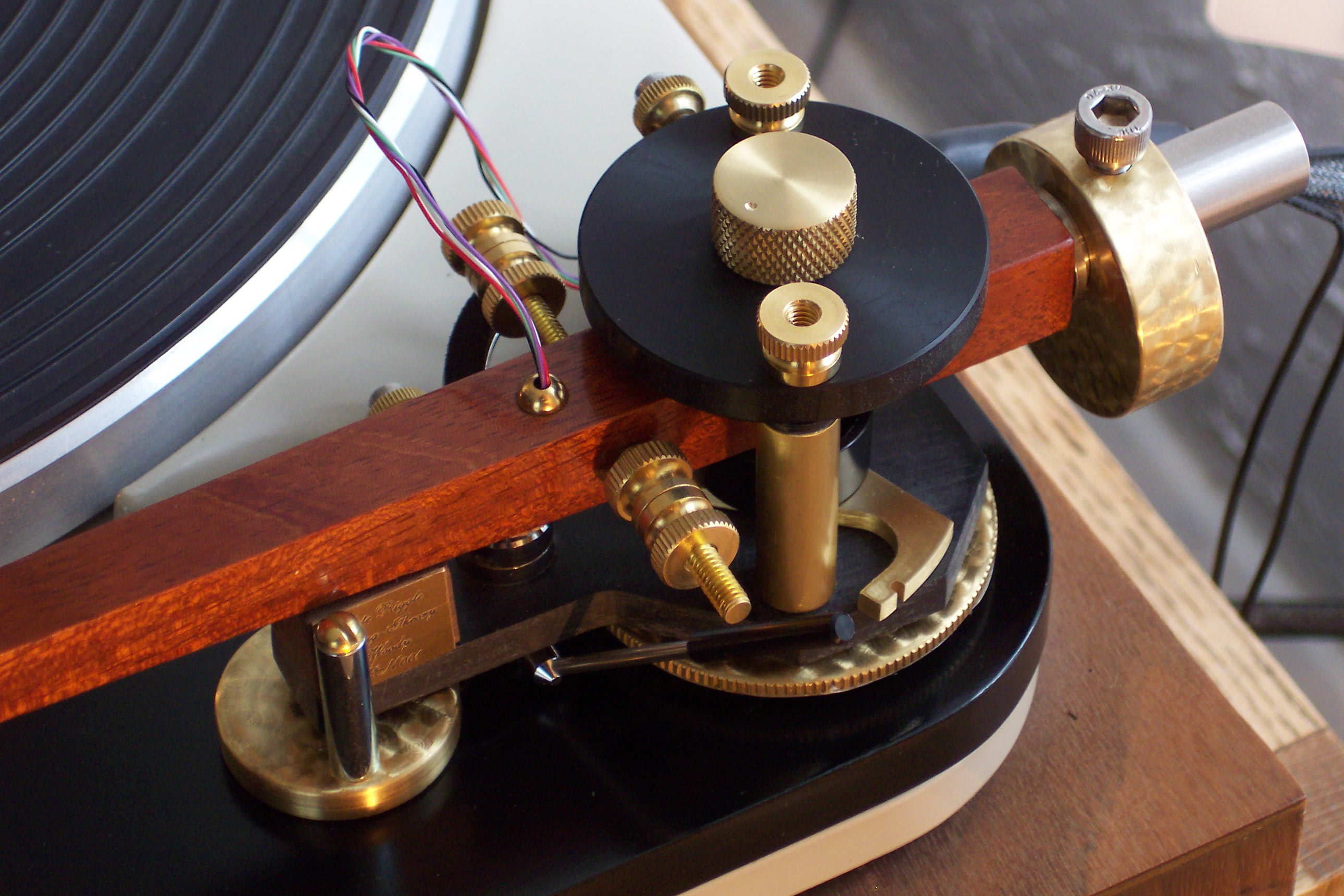
of the String Bearing Capsule:
in the photo to the left you will see the anti-skate adjustment knob
at the center of the upper platform. Also, you will see the two knurled nuts which hold down the upper platform. Coming
in horizontally from the far side of the tupper platform you will see the thumb screw which locks the bearing capsule
to which the anti-skate adjustment knob is screwed. To replace a fully or partially broken string bearing, proceed as follows:
Note the thumb screw that comes in from the side of the upper platform. Make sure this thumb screw is tight, then rotate the anti-skate knob to the left to unscrew the anti-skate knob from the bearing capsule (which is hidden by the anti-skate knob). Set the anti-skate knob aside for re-use. At this point you will see the bearing capsule centered in its hole in the top plate.
To loosen the bearing capsule from the upper platform, loosen the thumb screw that comes in from the side of the upper platform.
To remove the upper platform remove the two knurled nuts that hold the upper platform to its threaded support posts, lift the upper platform off the support posts, and set the upper platform aside for re-use.
If the string bearing has been fully broken, the bearing capsule will fall away from the brass button which secures the bearing string to the top of the arm wand.
If the string bearing has been partially broken, the bearing capsule will remain attached to the brass button which secures the bearing string to the top of the arm wand.
You now have access to the hold-down screws of the keeper that holds the lower brass button in place. Use a small flat blade screwdriver to remove these hold-down screws. Slide the keeper away and set it aside.
If the string bearing is only partially broken you will be able to lift on the bearing capsule to remove the brass button from its recess in the tone arm wand. If the string bearing is fully broken, pry the existing brass button out of the recess in the arm wand using a fine pointed implement (awl, ice pick, paper clip end) inserted into one of the button holes. Set the existing brass button aside.
The lower brass button of the new bearing capsule will press into the circular recess of the tonearm wand with some force. Push down on the bearing capsule to do this.
Replace the keeper that holds down the lower button. Use a minimum of torque when tightening the tiny screws into the arm wand. This will avoid stripping the threads of the wood, which may be reused many times unless stripped by excess torque.
Work the upper platform over the replacement bearing capsule and the threaded posts.
Lift up on the bearing capsule to expose some of its threads, and tightly snug the thumb screw of the upper platform to hold the capsule threads exposed.
Screw the anti-skate knob onto the capsule finishing up with sufficient torque to lock the knob onto the capsule.
Loosen the thumbscrew which locks the anti-skate knob, and push the anti-skate knob down onto the upper platform before re-snugging the set screw. From this point on, the set screw does not need to be very snug.
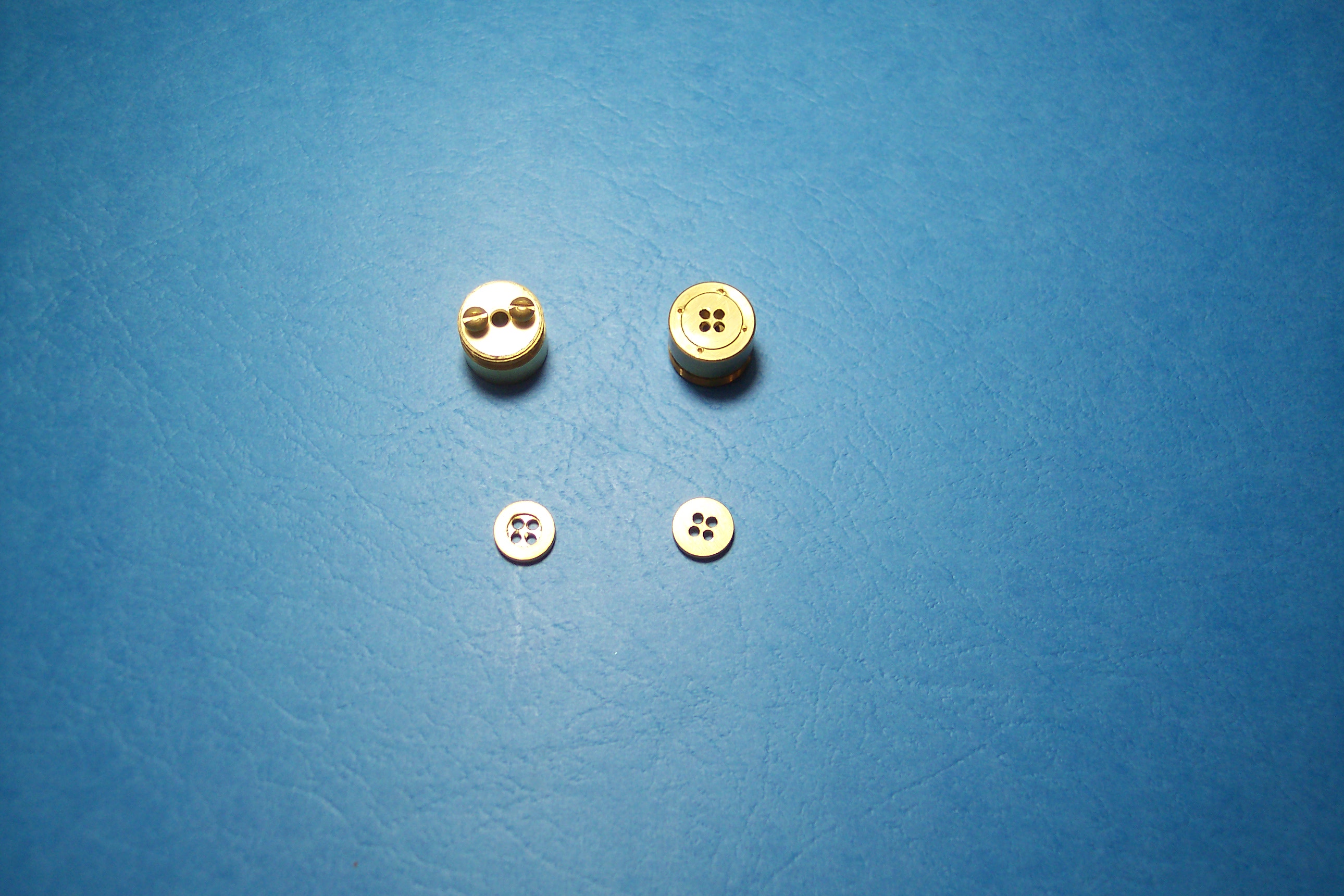
At this point you should check the set up of the lift/lower mechanism, check tracking force, reset the anti-skating force, and be able to use the Woody tonearm again. It is a good idea to reset VTA after a bearing change. Restringing a Woody Stringtheory Bearing: The photo below shows the bearing capsule and the lower brass button. Each
is shown upright and upside down.
The photo below shows an example of the commercially available braided fishing
line used for the string bearing thread. The material used for the thread has the trade name Dyneema (tm), which we understand
to be a high density polyethylene with strength 40 percent higher than Kevlar. 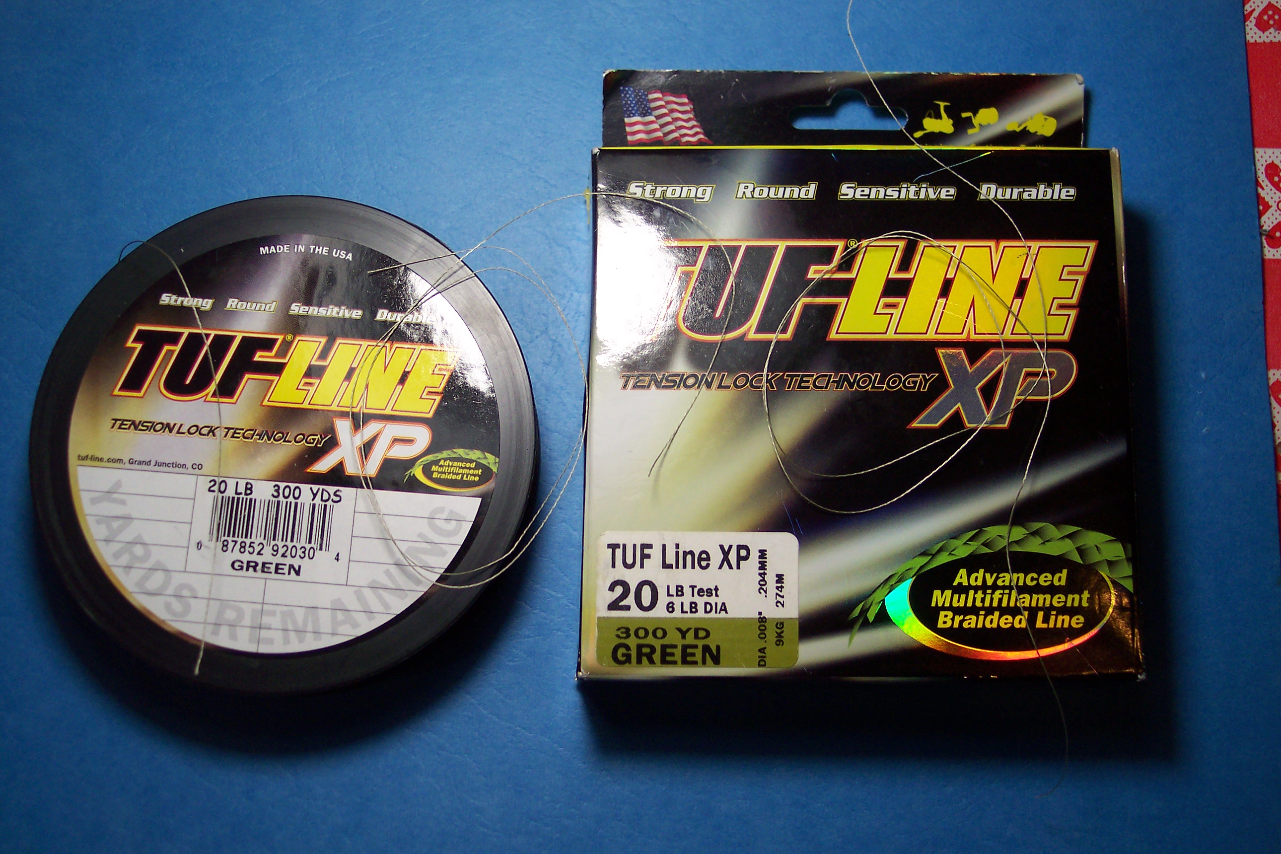
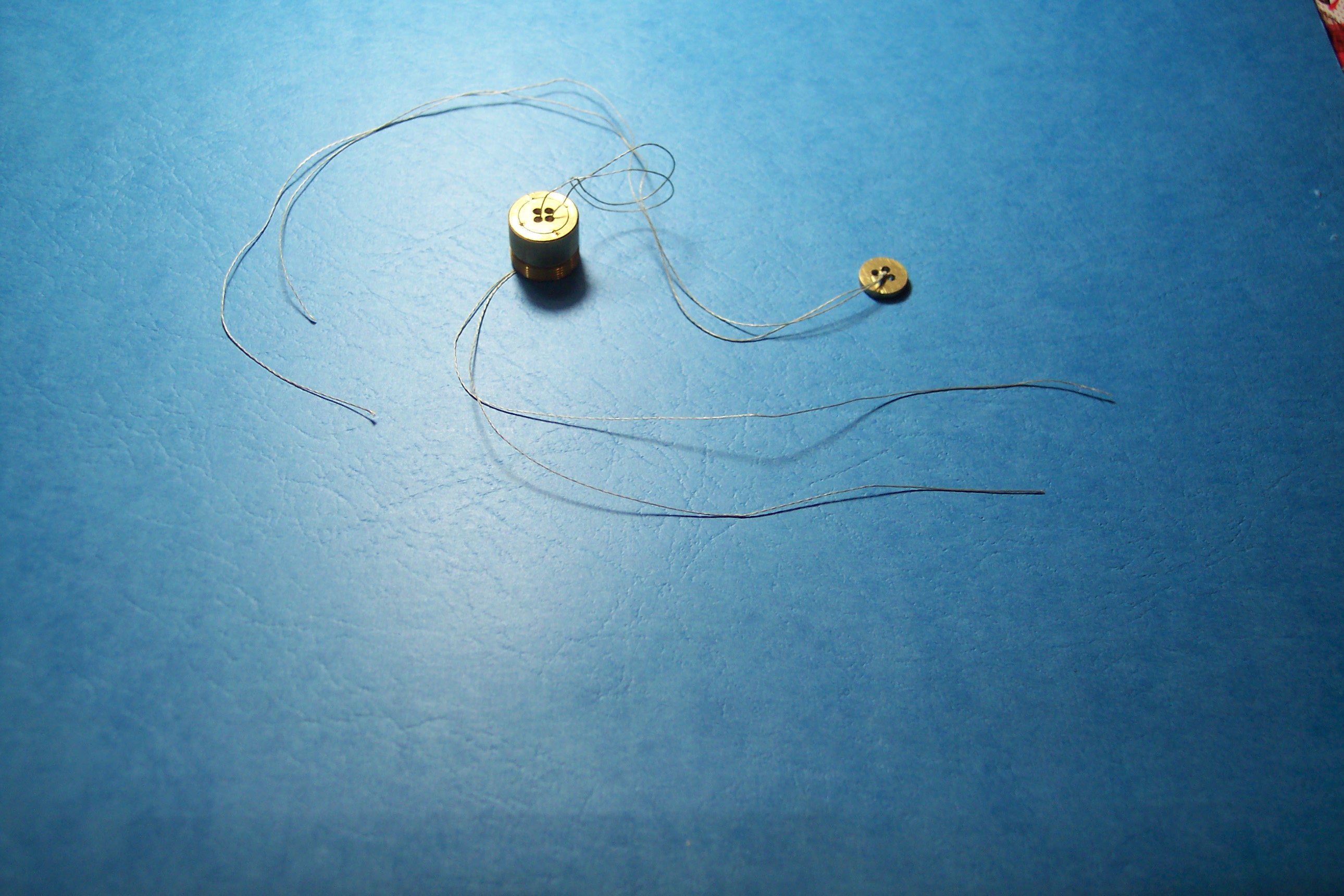
In the photo below, the bearing capsule and the lower brass button have each been threaded with 16 inch lengths of thread. The Dyneema (tm) thread is difficult to cut cleanly. We get clean cuts with a sharp Exacto knive, by laying the thread on a firm surface, and running the knife over the thread with substantial force.
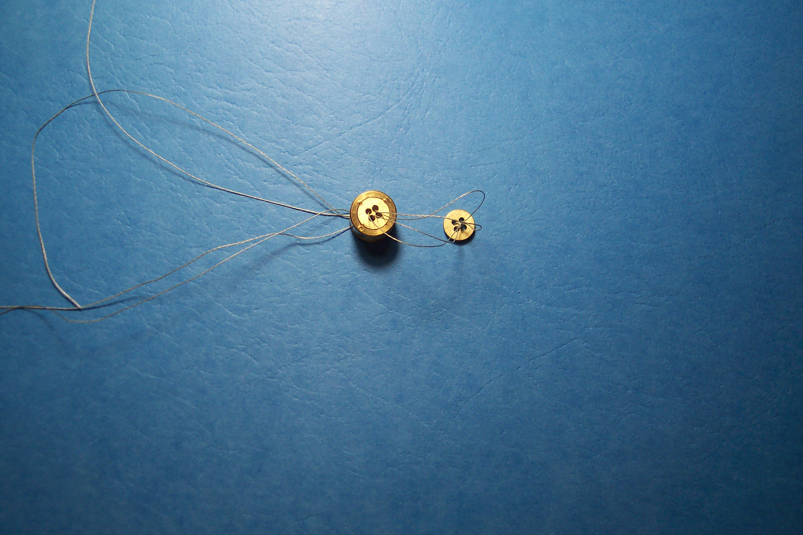
Taking the button first, note that the two ends of one of the thread lengths have been threaded through two adjacent holes on the smooth side of the button. Each of these ends has been threaded back up through a remaining empty hole. Also note that a lark's-head hitch (a type of knot, also called a cow hitch or a girth hitch) has been made in the string, and that the two free ends of the string have been threaded through the so called larks-head.
Also in the photo below, note that the second length of thread has been threaded through two adjacent holes in the bearing capsule, and that a lark's-head has been made in the thread. 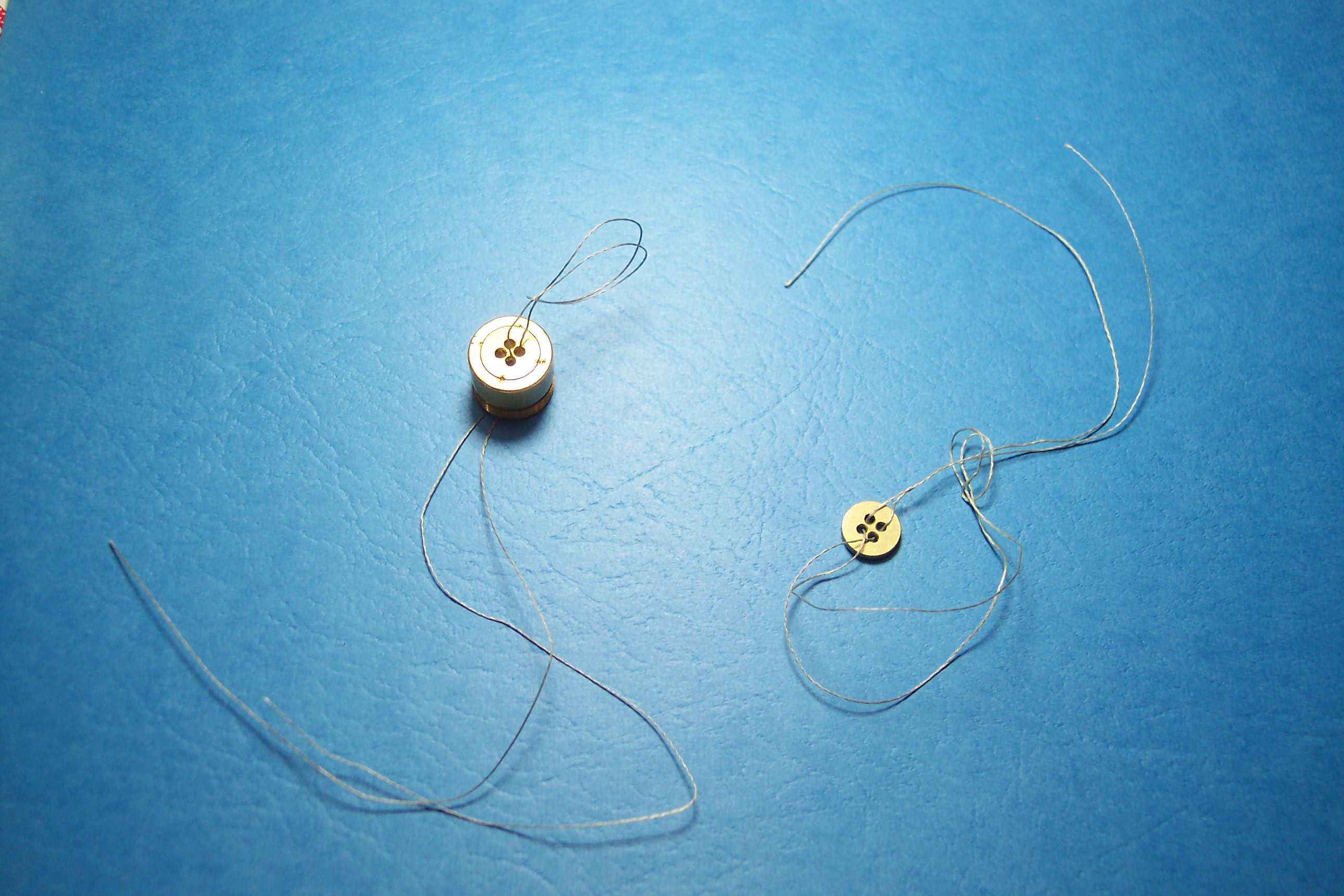
In the following photo notice that the lark's-head hitch for the button has been snugged down, with the knot centered at the center of the button. Also notice that the two free thread ends of the button thread have been threaded through the lark's-head of the bearing capsule thread.
In the following photo you will see that the lark's-head hitch of the bearing capsule thread has been drawn tight around the threads associated with the button, and that said hitch has been slid down the button threads to a position tight against the lark's-head hitch of the button thread. Then the button thread ends have been threaded into the two free holes of the capsule button.
In the photo below, you will see that the four threads emanating from the single hole in the top end of the bearing capsule have been pulled up tight, twisted, and wrapped under the head of one of the thread retaining screws at the top of the bearing capsule. The thread retaining screw has been tightened.
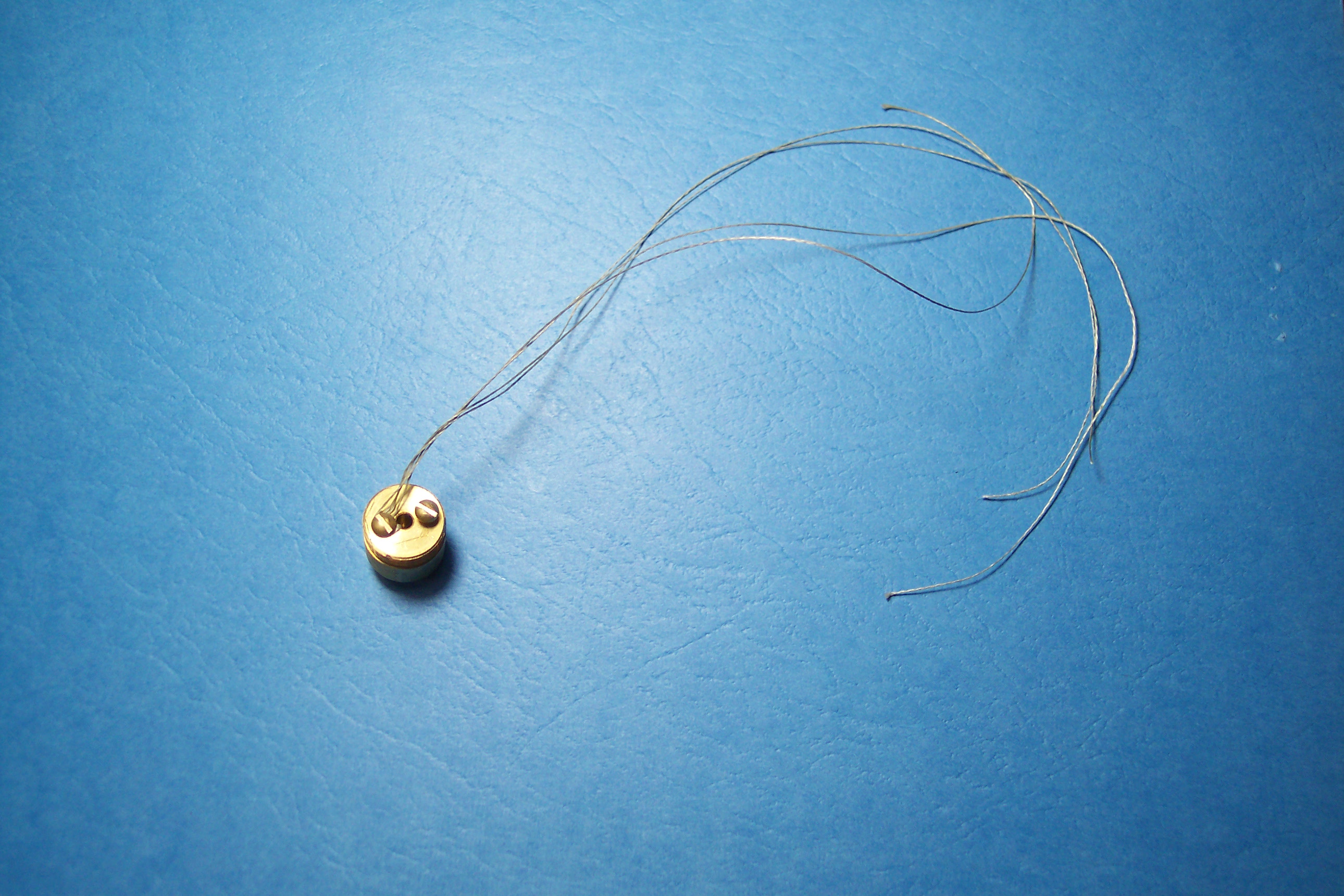
In the next photo you will see that the thread has been once again twisted and wrapped under the head of the second thread retaining screw, which has been tightened. Also notice that the four thread ends have been cut off with a sharp Xacto knife bearing against the top of the bearing capsule.
In the following photo you see a side view of the finished bearing capsule, including the lower button. Notice the small dimensions of the string bearing proper. When the capsule has been installed into the tonearm assembly, it will be intentionally, momentarily, placed under a modest amount of tension to give it a preliminary stretching. Then the bearing will be ready for use.
Finally, in the image below, please find a diagram showing the entire flow of the process of threading a bearing capsule. We apologize for the quality of the art work, but justify this by observing that we prefer building excellent tonearms to doing excellent art work.
Permission for Hobbyists to Use the Stringtheory (tm) Bearing in Their Own Creations:
DIY audio is one of the great hobbies, and one which we have participated in for a lifetime, and one which we encourage. For that reason we encourage analog audio hobbyists to take advantage of the Stringtheory (tm) bearing design for non-commercial purposes if it will further their enjoyment of the hobby.
 |