|
 "If you can
change a tone arm,
you can install the VTAF." - Joseph P Horvath II VTAF™ INSTALLATION INSTRUCTIONS Congratulations! You will love your VTAF. We are impressed with the control VTA adjustment on the fly provides over sound quality. Great records become greater. Many unlistenable albums become listenable. With some records the difference is night and day. Please see the figures and the REGA specifications at the end of these instructions before proceeding.Benefits of the VTAF:
Simplified transfer of the tone arm system from one turntable to another (requires a VTAF bushing and vertical guide in each turntable... additional bushing and vertical guide separately available for $49).
TURNTABLES AND TONE ARMS COMPATIBLE with the VTAF™: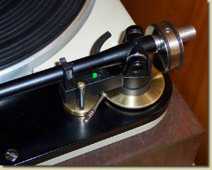 Figure 1: VTAF™ on a Thorens TD125 The Standard VTAF™ (for post mounted arms) is compatible with the
REGA™ RB250, RB300 and RB600, and modifications based on these arms. The Three Point Mount VTAF is compatible with the
Rega RB251, RB301, RB700, RB900, and RB1000 arms. Generally speaking, the VTAF can be adapted to
most tonearms that have the pivot center on the same vertical axis as the mounting system. Contact
us if you have a different REGA™ arm model, or any arm you would like to apply the VTAF™ to, and we will compare
notes. Generally speaking, the VTAF can be adapted to most tonearms that have the pivot center on the same vertical
axis as the mounting system. 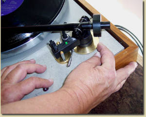 Figure 2: Depressing a Spring Mounted Chassis to adjust VTA
The VTAF™ is also
compatible with any of the above REGA™ arms on a spring mounted chassis, like that of the Thorens™ TD125, 150,
160, and later Thorens tables, or other tables with spring mounted chassis. When adjusting VTA on the fly with a spring mounted
chassis, it may help to 1) gently press down on the chassis near the VTAF™ to move the chassis against its stops, 2)
make an adjustment, and 3) gently releases the chassis to its free floating position; this is easy to do, and quickly becomes
second nature. See Figure 2. Alternative versions of the VTAF™ are available for the Nottingham Spacedeck
with the Spacearm, the Spacedeck with Rega arms and Rega based arms including the Origin Live Silver, the Spacedeck with the
Origin Live Encounter arm, and the Nottingham Log with Rega arms, Rega Based arms including the Origin Live Silver, and the
Origin Live Encounter arm. Adapters are available for many arms with smooth mounting posts. PARTS PROVIDED:The standard VTAF™ for Rega arms has the following parts (see Fig. 3):
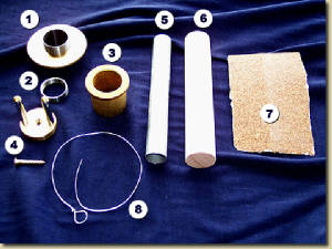 Figure 3: VTAF™ parts
1)Adjuster Screw and Adjuster Wheel 2)Capture nut 3)Armboard Bushing 4)Vertical Guide 5)and 6)Sanding Forms 7)Sandpaper 8)Wire Compass Expendable tools included for use in installation are:
In addition, small brass shims in thicknesses of .010", .020", 030", .040" and .050" are included for shimming under the rear of the phone cartridge if a lower VTA setting is needed than provided by the basic setup of the VTAF™.
ACHIEVING the BEST VTA ADJUSTMENT RANGE:The best approach to achieving the right VTA range is to do a simple installation of the VTAF™. Then, with the VTAF™ at its lowest setting, and the stylus in the groove of a standard LP record, check to see it the rear of the cartridge is a touch lower than level. If not, you may shim between the rear of the cartridge and the headshell with one of the precision shims included with the VTAF™. The precision shims are provided in thicknesses of .010", .020", .030", .040", and .050". Each shim has the same effect as lowering the tone arm pedestal about .10"
This is only
a rule of thumb, however, because the stylus rake angle varies from cartridge model to cartridge model, and production unit
to production unit; so even if your measurements don’t add to somewhere near between 2 inches, it is still worth doing
the simple installation, and then trying the system out with a wide range of records, to determine by audible results, what
change, if any, may need to be made. For a range of turntables the elevation difference
between the top of the record mat and the top of the arm board ranges from about 1 inch to about 1.25 inches. Cartridges tend
to range in height from about .7 inches to about 1 inch, from the tip of the stylus to the top of the cartridge, where the
cartridge meets the head shell. Thus, we should not be surprised if the sum of these dimensions falls within, or even outside,
the range from 1.7 inches to 2.25 inches. In the unlikely case the VTAF™ is found to
be unable to sufficiently raise the tone arm pedestal for some records, the cartridge may be shimmed at the front with one
of the precision brass cartridge shims supplied, or washer shaped precision shims can be supplied by Pete Riggle Audio to
raise the VTAF™ bushing. A more likely case is that the simply installed VTAF™ will not able to sufficiently lower the tone arm pedestal for some records. In this case, one or more of several adjustment options can be employed. They are:
All of the above corrections are additive, and may be used in combination to find the easiest remedy if the tone arm pedestal needs to go lower.
INSTALLING the VTAF™ BUSHING:The VTAF™ bushing needs to be installed with a slightly loose fit in a 1.25"
nominal hole in the arm board or the turntable top deck. A 45 degree chamfer about .020" wide (or 1/2 mm) must be provided
at the top of the hole. It is more important to have the bushing flush with the arm board or top deck than it is to have it
snug in the hole. If the hole is too snug, and not aligned right, it may keep the bushing from resting flush with the arm
board or deck. In this case, remove from the hole wall the material which is keeping the bushing from resting flush. Marking out the 1.25" Diameter VTAF™ Bushing Mounting Hole:
Look at Figures 1, 7 and 8 to get a general notion of the installation. For REGA arms such as the RB250
and others that have the same geometry, the distance from the center of the turntable spindle to the center of mounting hole
(called the mounting distance) needs to be 222.8 mm or 8.78 inches (approximately 8-25/32 inches). An error of 1/16 inch either
way will not hurt. Final adjustment of the cartridge body using a cartridge alignment protractor, or other means, will accommodate
small variations in mounting distance. The bushing mounting hole can be made in a blank arm board or blank
turntable deck. The bushing mounting hole can also be made by enlarging an existing mounting hole.
MARKING OUT a PRE-DRILLED ARM BOARD:A mounting hole already drilled for a REGA™ arm requires enlargement to accept the
VTAF™ bushing. The standard REGA™ mounting hole diameter is 25 mm. This is just under one inch (25.4 mm). The
hole diameter for the VTAF™ bushing needs to be 1.25" (31.75mm) nominal. It is worth checking that an existing mounting hole for a REGA™arm is centered correctly, with a mounting distance of 222.8 mm or 8.78 inches (approximately 8-25/32 inches) from the center of the turntable spindle to the center of the arm mounting hole. Using a good quality rule or metal measuring tape, measure the distance from your best guess turntable spindle center to the close edge of the existing hole. Hold the rule level. Use a flat rectangular object, such as a business card or credit card to establish the vertical line to the edge of the hole. To the measured distance add half the diameter of the existing mounting hole. The resulting sum is the measured existing mounting distance, which should be between 8-23/32 inch and 8-27/32 inch. If the existing hole is not centered within this range, make an appropriate adjustment. Use a sharp pencil to mark the arm board top with the perimeter of the 1.25 inch diameter mounting hole. You can use a commercial 1.25 inch diameter circle template, or the 1.25 inch diameter body of the bushing, or you can just use a good ruler to mark at a number of locations around the existing hole the distance from the edge of the existing hole to the edge of the 1.25" hole.
MARKING OUT AN UNDRILLED ARM BOARD:A temporary layer of masking tape makes a good marking surface for the top of the arm board or turntable deck. An arc needs to be drawn on the masking tape at the 8.78" mounting distance from the center of the turntable spindle to the center of the mounting hole. This arc is not the final measurement, but just a target. The final measurement will be checked precisely. A special compass, such as the one built into the Clearaudio™
tone arm protractor is useful for this job, but there are less elegant alternatives which are completely satisfactory. A strip of wood drilled for the spindle at one end and a medium slip fit to a sharp pencil at the other end, with 8.78 inches between centers serves well. An expendable 12" length of steel wire (provided) may be used to
form a wire compass. See Figure 4. The loop for the turntable spindle is already formed. Wrap the other end of the wire around
a sharp pencil. Mark the arm board at a point which is near the desired mounting center and is 8.78 inches from the center
of the turntable spindle. Adjust your compass to reach this mark, holding the wire taut and level and the pencil vertical.
Strike the arc, holding the wire taut and level and the pencil vertical. Now take the REGA™ tone arm system in your hands and temporarily locate it so the center of the mounting stud is located over the arc struck at the mounting distance.  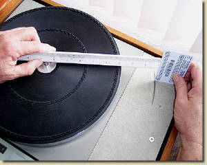 Figure 4: Checking the Mounting Distance
MAKING the BUSHING MOUNTING HOLE: If a mounting hole already exists, it can be enlarged to 1.25 inch diameter by using 60 grit
abrasive paper (provided) wrapped around one of two cylindrical sanding forms (provided), as discussed below, or with a Forstner
drill bit, as discussed below.
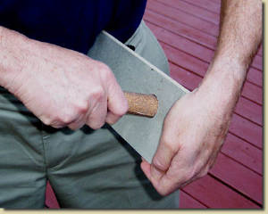 Figure 5: Abrasive Paper and Dowel in Use Enlarge
the hole slowly and carefully (with the 60 grit abrasive paper over a cylindrical sanding form) to the final fit of hole with
the 1.25 inch diameter. Check frequently along the way, until the bushing slips into the hole with a little clearance.
See Figure 5. Use careful strokes of the abrasive with the dowel perpendicular to the plane of the arm board or deck. Keep
moving around the perimeter to assure uniform progress. Transition to the larger diameter dowel when it is practical. Do not
make the hole too large. Do not force the bushing into a hole that is too tight. As you approach the final diameter remove
just a bit of material at a time with the sandpaper, uniformly around the perimeter, until you achieve a fit with a little
clearance. Even if you start with a 24 mm mounting hole you can enlarge the hole to
the desired 1.25 inch diameter in less than 20 minutes. You can do it. Try the bushing in the hole frequently as the hole
approaches the desired fit with the bushing. Little jobs like this are part of the craft and hobby of audio. In most cases the hole can be drilled with a 1.25 inch Forstner bit, using a drill press, even if an existing hole is present. The Forstner bit guides off its outer edge. See Figure 6. Do a little test drilling before you go for the gold. If you have to drill an unremovable top deck of a turntable, you will need a block under the deck to support your work, and an extra set of hands to hold the turntable level while you lower the drill. 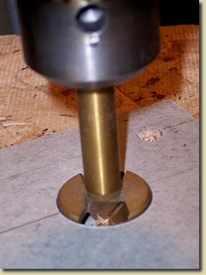 Figure 6: Forstner Bit in Use
The hole
drilled by a 1.25" Forstner bit may be too snug to accept the bushing, requiring that the hole be slightly enlarged manually,
all around its perimeter, with a piece of 60 grit aluminum oxide abrasive paper wrapped around a length of dowel as discussed
above. Work slowly and carefully, using the largest dowel diameter available that will enter the hole with 60 grit abrasive
paper wrapped around it. Make Sure the Bushing Rests Flat Against the Arm Board or DeckAs mentioned earlier, what we want is for the top of the bushing to be dead level when the top of the record mat is dead level.
INSTALLING the ADJUSTER SCREW and ADJUSTER WHEEL on the REGA™ TONE ARM:The adjuster wheel has a finished top and an unfinished bottom. The finished top is jeweled (engine turned or damascened) and a drilled index mark. 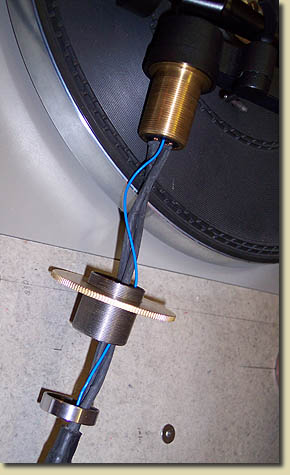 Figure 7: VTAF™ Adjuster Screw and Capture Nut
In the same manner, run the
adjuster screw capture nut up the cables, start it carefully on the REGA™ arm mounting stud, and snug it loosely against
the adjuster screw. Spin the adjuster wheel until it is near the base of the tone arm pedestal, but not in contact with the
pedestal. We don’t want the adjuster wheel to be jammed against the base of the tone arm pedestal after we have tightened
the adjuster screw capture nut. Rotate the adjuster screw and wheel together until the index mark on the face of the adjuster wheel will be at the right side of the tone arm when facing the turntable, when the adjuster wheel makes contact with the tone arm base. Now wrap your fingers around the capture nut and the adjuster screw, squeeze, and tighten the capture nut with your fingers as tightly as you can. During this procedure do not put force on the arm pivot bearing system. 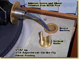 Figure 8: VTAF™ Adjuster Screw Ready for Insertion into
Bushing Now thread the RCA terminals of the phono cables, and the ground wire, one at a time, through the bushing from the top of the bushing. Work the cable through the bushing and work the RCA terminals and the ground wire out the rear of the turntable base. Continue feeding wire through the bushing until the adjuster screw enters the bushing.
For a wood arm board or turntable deck, the vertical guide screws to the top of the arm
board or deck with a single No. 6 flat headed brass wood screw (included). Refer to Figure 7. The screw hole for the vertical
guide mounting screw should be centered 1-3/16 inches forward of the front edge of the VTAF™ bushing. To locate this
hole from side to side, place the VTAF™ vertical guide on the arm board in its approximate final location, cradling
the horizontal projection of the tone arm pedestal. Rotate the vertical guide until there is no free play between the vertical
guide elements and the pedestal projection. Move the guide from side to side until the tone arm looks right when locked in
the arm rest. Mark the perimeter of the vertical guide base. Lift the arm out of the bushing temporarily. Mark the center
of the vertical guide and drill a 3/32 inch pilot hole (.100 inch is even better if available). Tighten the guide attachment
screw so that the vertical guide pivots snugly against friction with the arm board. Rotation of the vertical guide removes
play between the REGA™ pedestal projection, and the vertical guide elements that prevent rotation of the pedestal. Insert
the adjuster screw back into the bushing. Rotate the vertical guide to remove the play between the vertical guide elements
and the tone arm pedestal projection. Align the cartridge using a protractor or by making sure that a straight line from the
turntable spindle center to the stylus tip is nearly parallel to the front edge of the cartridge at various points as the
arm swings over the record. The arm is now completely installed. Connect the phono leads to your phono stage and enjoy the music.
USING the VTAF™:The adjustment range of the VTAF™ exceeds 1/2 inch. Start by setting the adjuster
wheel to get the cartridge body approximately level. Listen to your records and make adjustments as you
go. With the tone arm pedestal set too low, expect the bass to be on the bloated side, and the highs to be diminished and
unexceptional. With the pedestal set too high, expect the bass to be thin and the highs to be harsh. In the middle ground
you will find appropriate taut bass, and enticing highs. Some records are not redeemable, but many are.
Your best records can be surprisingly good at the right VTA. Each complete turn of the adjuster wheel changes
the height of the tone arm pedestal by exactly 25 thousandths of an inch. The index mark on the adjuster wheel will help you
count turns, but there is a much better way, which is easy to do even in low light, a help for those with vision problems.
To easily determine and repeat VTA settings, find or purchase a standard deck of plastic coated playing
cards to use as a thickness gage. See Figure 9. The cards are durable, flexible, easy to use, and won’t mark your equipment.
Each card is about 10 thousandths inch thick. So complete each turn of the adjuster wheel is equivalent to about 2-1/2 cards
thickness. But why bother with inches, when you can count and record the VTA setting in playing cards? When you get an album dialed in, write the number of playing cards somewhere on the record jacket and be done with it. The next time you pull out the album, spin the wheel to the desired setting as indicated by the playing cards. Give us some feedback. There is a 90 day return policy on your VTAF™, with full refund of except for the original shipping amount.
REGA RB250 ARM TECHNICAL SPECIFICATIONS:
Per Pete Riggle Audio
Distance from arm pivot to cartridge end of arm: 245 mm. Stylus is typically
5 mm (approx. .2 inches, approx. 3/16" inch) inboard of the end of the arm.
Values calculated using the Baerwald
(peak distortion equivalence) method are 240.2 mm effective arm length, 222.97 mm mounting distance, 17.23 mm overhang, and
22.894 degrees offset angle. For the Baerwald method, The null radii, the radii at which the cartridge cantilever should parallel the record groove, are 66 mm and 120.89 mm. SETUP FOR THE CORRECT VTA RANGE: The goal in setting up the VTAF is to get the cartridge body slightly low in the rear when the VTAF is at its lowest setting. This corresponds to a low VTA. The VTAF has more than .5" of adjustment range, so higher VTA values are easy to achieve. Where a height setup adjustment is required, there are several approaches described in the installation instructions.One approach is by shimming under the rear or front of the phono cartridge with precision brass shims provided in thicknesses of .010, .020, .030, .040, and .050 inches. Each .010 inches (.25 mm) of shim under the rear of the phono cartridge gives an effect equivalent to increasing the platter height or lowering the arm board by 1/8" (3.2 mm). Each .010 inches of shim under the front of the phono cartridge gives an effect equivalent to decreasing the platter height or raising the arm board by 1/8". MEASURING AND RESETTING VTA:Figure 9 shows how a deck of ordinary playing cards, not included, can serve as a thickness gage to measure, record, and repeat the preferred VTA setting of any record. 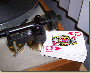 Figure 9: A Practical Method for Measuring and Repeating VTA Settings This is an excellent method for measuring, recording, and repeating VTA settings, working easily with poor vision or in low light. Each card is very close to 10 thousandths inch thick, providing more than adequate resolution for resetting VTA. But why keep track of pedestal height in inches, when it can more easily be recorded by playing card count? Simply mark on the record jacket the number of playing cards corresponding to the preferred VTA. |
|||||||||||||||||||||||||